Achieve non-contact temperature measurement and thermal imaging using MLX90641 and MK64FN1M0VDC12
Non-contact temperature measurement and thermal imaging

Published Sep 17, 2024
Click board™
IR Grid 4 Click
Dev. board
Clicker 2 for Kinetis
Compiler
NECTO Studio
MCU
MK64FN1M0VDC12
Captures and displays thermal images based on temperature variations within the 55° field of view
A
A
Hardware Overview
How does it work?
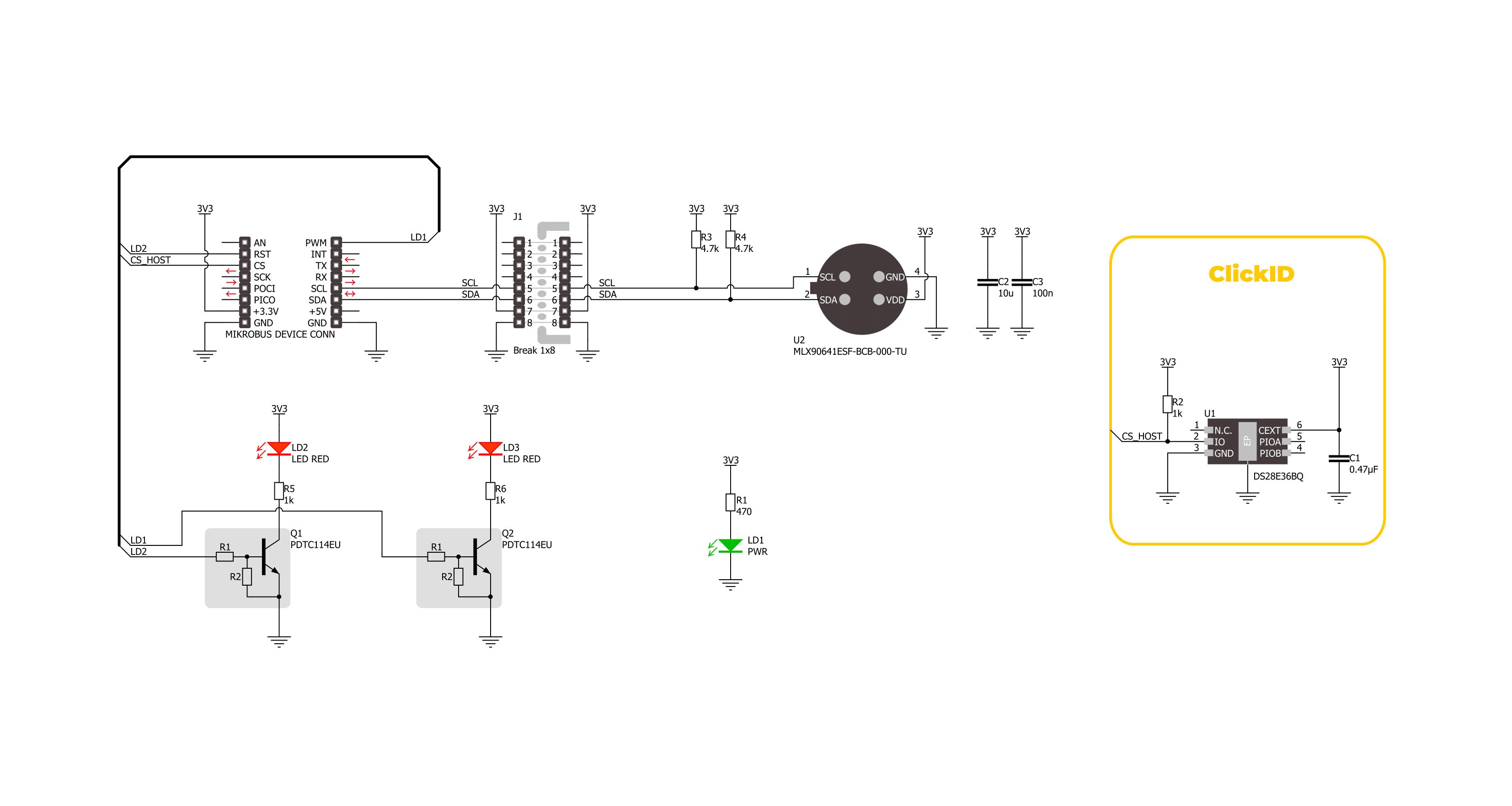
IR Grid 4 Click is based on the MLX90641, a fully calibrated thermal IR array from Melexis in an industry-standard 4-lead TO39 package with a digital interface and a 55° viewing angle. It captures temperature data across a two-dimensional 16x12 matrix (192 pixels) and provides this information as a digital output. It can accurately measure temperatures from -40°C to +300°C and ensures an accuracy of 1°C in typical measurement conditions. With its ability to accurately measure contactless thermal or thermal imaging, IR Grid 4 Click is ideal for high-precision non-contact temperature measurements, intrusion/movement detection, industrial temperature control of moving parts, a visual IR thermometer, and more. This Click board™ is designed in a unique format
supporting the newly introduced MIKROE feature called "Click Snap." Unlike the standardized version of Click boards, this feature allows the main sensor area to become movable by breaking the PCB, opening up many new possibilities for implementation. Thanks to the Snap feature, the MLX90641 can operate autonomously by accessing its signals directly on the pins marked 1-8. Additionally, the Snap part includes a specified and fixed screw hole position, enabling users to secure the Snap board in their desired location. IR Grid 4 Click uses a standard 2-wire I2C interface to communicate with the host MCU, supporting Standard mode with up to 1MHz of frequency clock. In addition to the I2C interface pins, this board also uses two user-configurable pins, LD1 and LD2,
paired with corresponding red LED indicators. These LEDs serve as customizable visual signals, allowing the user to indicate specific operational states of the main sensor, the MLX90641. The LEDs can be programmed to light up under certain conditions, such as when the sensor detects specific temperature thresholds or when it enters a particular mode, providing immediate visual feedback during operation. This Click board™ can be operated only with a 3.3V logic voltage level. The board must perform appropriate logic voltage level conversion before using MCUs with different logic levels. Also, it comes equipped with a library containing functions and an example code that can be used as a reference for further development.

Features overview
Development board
Clicker 2 for Kinetis is a compact starter development board that brings the flexibility of add-on Click boards™ to your favorite microcontroller, making it a perfect starter kit for implementing your ideas. It comes with an onboard 32-bit ARM Cortex-M4F microcontroller, the MK64FN1M0VDC12 from NXP Semiconductors, two mikroBUS™ sockets for Click board™ connectivity, a USB connector, LED indicators, buttons, a JTAG programmer connector, and two 26-pin headers for interfacing with external electronics. Its compact design with clear and easily recognizable silkscreen markings allows you to build gadgets with unique functionalities and
features quickly. Each part of the Clicker 2 for Kinetis development kit contains the components necessary for the most efficient operation of the same board. In addition to the possibility of choosing the Clicker 2 for Kinetis programming method, using a USB HID mikroBootloader or an external mikroProg connector for Kinetis programmer, the Clicker 2 board also includes a clean and regulated power supply module for the development kit. It provides two ways of board-powering; through the USB Micro-B cable, where onboard voltage regulators provide the appropriate voltage levels to each component on the board, or
using a Li-Polymer battery via an onboard battery connector. All communication methods that mikroBUS™ itself supports are on this board, including the well-established mikroBUS™ socket, reset button, and several user-configurable buttons and LED indicators. Clicker 2 for Kinetis is an integral part of the Mikroe ecosystem, allowing you to create a new application in minutes. Natively supported by Mikroe software tools, it covers many aspects of prototyping thanks to a considerable number of different Click boards™ (over a thousand boards), the number of which is growing every day.

Microcontroller Overview
MCU Card / MCU

Architecture
ARM Cortex-M4
MCU Memory (KB)
1024
Silicon Vendor
NXP
Pin count
121
RAM (Bytes)
262144
Used MCU Pins
mikroBUS™ mapper
Take a closer look
Click board™ Schematic
Step by step
Project assembly

Start by selecting your development board and Click board™. Begin with the Clicker 2 for Kinetis as your development board.


Software Support
Library Description
This library contains API for IR Grid 4 Click driver.
Key functions:
irgrid4_get_measurement- This function reads the RAM frame data and calculates ambient temperature and a 16x12 IR grid object temperature.irgrid4_set_refresh_rate- This function sets the IR data refresh rate.irgrid4_enable_led1- This function enables the LED1.
Open Source
Code example
The complete application code and a ready-to-use project are available through the NECTO Studio Package Manager for direct installation in the NECTO Studio. The application code can also be found on the MIKROE GitHub account.
/*!
 * @file main.c
 * @brief IR Grid 4 Click example
 *
 * # Description
 * This example demonstrates the use of IR Grid 4 Click by reading and displaying
 * the ambient and object temperature measurements in a 16x12 pixels grid format.
 *
 * The demo application is composed of two sections :
 *
 * ## Application Init
 * Initializes the driver and performs the Click default configuration.
 *
 * ## Application Task
 * Reads the ambient and object temperature measurements every 500ms and displays
 * the results on the USB UART in a form of a 16x12 pixels grid.
 *
 * @author Stefan Filipovic
 *
 */

#include "board.h"
#include "log.h"
#include "irgrid4.h"

static irgrid4_t irgrid4;
static log_t logger;

void application_init ( void )
{
    log_cfg_t log_cfg;  /**< Logger config object. */
    irgrid4_cfg_t irgrid4_cfg;  /**< Click config object. */

    /**
     * Logger initialization.
     * Default baud rate: 115200
     * Default log level: LOG_LEVEL_DEBUG
     * @note If USB_UART_RX and USB_UART_TX
     * are defined as HAL_PIN_NC, you will
     * need to define them manually for log to work.
     * See @b LOG_MAP_USB_UART macro definition for detailed explanation.
     */
    LOG_MAP_USB_UART( log_cfg );
    log_init( &logger, &log_cfg );
    log_info( &logger, " Application Init " );

    // Click initialization.
    irgrid4_cfg_setup( &irgrid4_cfg );
    IRGRID4_MAP_MIKROBUS( irgrid4_cfg, MIKROBUS_1 );
    if ( I2C_MASTER_ERROR == irgrid4_init( &irgrid4, &irgrid4_cfg ) )
    {
        log_error( &logger, " Communication init." );
        for ( ; ; );
    }

    if ( IRGRID4_ERROR == irgrid4_default_cfg ( &irgrid4 ) )
    {
        log_error( &logger, " Default configuration." );
        for ( ; ; );
    }

    log_info( &logger, " Application Task " );
}

void application_task ( void )
{
    float image[ 192 ] = { 0 };
    float ambient_temp = 0;
    if ( IRGRID4_OK == irgrid4_get_measurement ( &irgrid4, &ambient_temp, image ) )
    {
        log_printf( &logger, " Ambient temperature: %.2f degC\r\n", ambient_temp );
        log_printf( &logger, "--- Object temperature image ---\r\n" );
        for ( uint8_t pixel_cnt = 0; pixel_cnt < 192; pixel_cnt++ )
        {
            log_printf( &logger, "%.2f", image[ pixel_cnt ] );
            if ( 15 == ( pixel_cnt % 16 ) )
            {
                log_printf( &logger, "\r\n" );
            }
            else
            {
                log_printf( &logger, " | " );
            }
        }
        log_printf( &logger, "--------------------------------\r\n" );
    }
}

int main ( void )
{
    /* Do not remove this line or clock might not be set correctly. */
    #ifdef PREINIT_SUPPORTED
    preinit();
    #endif

    application_init( );

    for ( ; ; )
    {
        application_task( );
    }

    return 0;
}

// ------------------------------------------------------------------------ END
Additional Support
Resources
Category:Temperature & humidity


