Optimize performance with accurate current sensing using AD8616 and ATmega2560
The future of current monitoring!

Published Feb 14, 2024
Click board™
Ammeter Click
Dev. board
Arduino Mega 2560 Rev3
Compiler
NECTO Studio
MCU
ATmega2560
Our advanced ammeter provides real-time measurement of electric currents, empowering you with instant and accurate data to optimize efficiency and ensure safe operations
A
A
Hardware Overview
How does it work?
Ammeter Click is based on the AD8616, a precision 20MHz CMOS rail-to-rail input/output operational amplifier from Analog Devices. It is a dual single-supply amplifier featuring very low offset voltage, wide signal bandwidth, and low input voltage and current noise. The AD8616 uses a patented trimming technique that achieves superior precision without laser trimming. Two onboard screw terminals labeled probe+ and probe-are bringing in the current, which then passes through a shunt resistor. A voltage proportional to the strength of the current is generated across the resistor, which is then processed in the operational
amplifier. The voltage amplified through the AD8616 can be directly monitored through the AN pin of the mikroBUS™ socket. One of the main features of the Ammeter Click is the MCP3201, a 12-bit A/D converter with the SPI serial interface from Microchip. This A/D converter has a sampling rate of up to 100ksps and has an onboard sample and hold circuitry. It provides a single pseudo-differential input with maximum differential nonlinearity at ±1LSB. The AD8616 fed the amplified current to this A/D convertor, which gets the 2.048V reference voltage from the MAX6106, a micropower low-dropout high-output-current
voltage reference from Analog Devices. The MCP3201 outputs digital value through the mikroBUS™ socket SPI interface to the host MCU. This Click board™ can operate with either 3.3V or 5V logic voltage levels selected via the PWR SEL jumper. This way, both 3.3V and 5V capable MCUs can use the communication lines properly. Also, this Click board™ comes equipped with a library containing easy-to-use functions and an example code that can be used, as a reference, for further development.

Features overview
Development board
Arduino Mega 2560 is a robust microcontroller platform built around the ATmega 2560 chip. It has extensive capabilities and boasts 54 digital input/output pins, including 15 PWM outputs, 16 analog inputs, and 4 UARTs. With a 16MHz crystal
oscillator ensuring precise timing, it offers seamless connectivity via USB, a convenient power jack, an ICSP header, and a reset button. This all-inclusive board simplifies microcontroller projects; connect it to your computer via USB or power it up
using an AC-to-DC adapter or battery. Notably, the Mega 2560 maintains compatibility with a wide range of shields crafted for the Uno, Duemilanove, or Diecimila boards, ensuring versatility and ease of integration.

Microcontroller Overview
MCU Card / MCU

Architecture
AVR
MCU Memory (KB)
256
Silicon Vendor
Microchip
Pin count
100
RAM (Bytes)
8192
You complete me!
Accessories
Click Shield for Arduino Mega comes equipped with four mikroBUS™ sockets, with two in the form of a Shuttle connector, allowing all the Click board™ devices to be interfaced with the Arduino Mega board with no effort. Featuring an AVR 8-bit microcontroller with advanced RISC architecture, 54 digital I/O pins, and Arduino™ compatibility, the Arduino Mega board offers limitless possibilities for prototyping and creating diverse applications. This board is controlled and powered conveniently through a USB connection to program and debug the Arduino Mega board efficiently out of the box, with an additional USB cable connected to the USB B port on the board. Simplify your project development with the integrated ATmega16U2 programmer and unleash creativity using the extensive I/O options and expansion capabilities. There are eight switches, which you can use as inputs, and eight LEDs, which can be used as outputs of the MEGA2560. In addition, the shield features the MCP1501, a high-precision buffered voltage reference from Microchip. This reference is selected by default over the EXT REF jumper at the bottom of the board. You can choose an external one, as you would usually do with an Arduino Mega board. There is also a GND hook for testing purposes. Four additional LEDs are PWR, LED (standard pin D13), RX, and TX LEDs connected to UART1 (mikroBUS™ 1 socket). This Click Shield also has several switches that perform functions such as selecting the logic levels of analog signals on mikroBUS™ sockets and selecting logic voltage levels of the mikroBUS™ sockets themselves. Besides, the user is offered the possibility of using any Click board™ with the help of existing bidirectional level-shifting voltage translators, regardless of whether the Click board™ operates at a 3.3V or 5V logic voltage level. Once you connect the Arduino Mega board with Click Shield for Arduino Mega, you can access hundreds of Click boards™, working with 3.3V or 5V logic voltage levels.

Used MCU Pins
mikroBUS™ mapper
Take a closer look
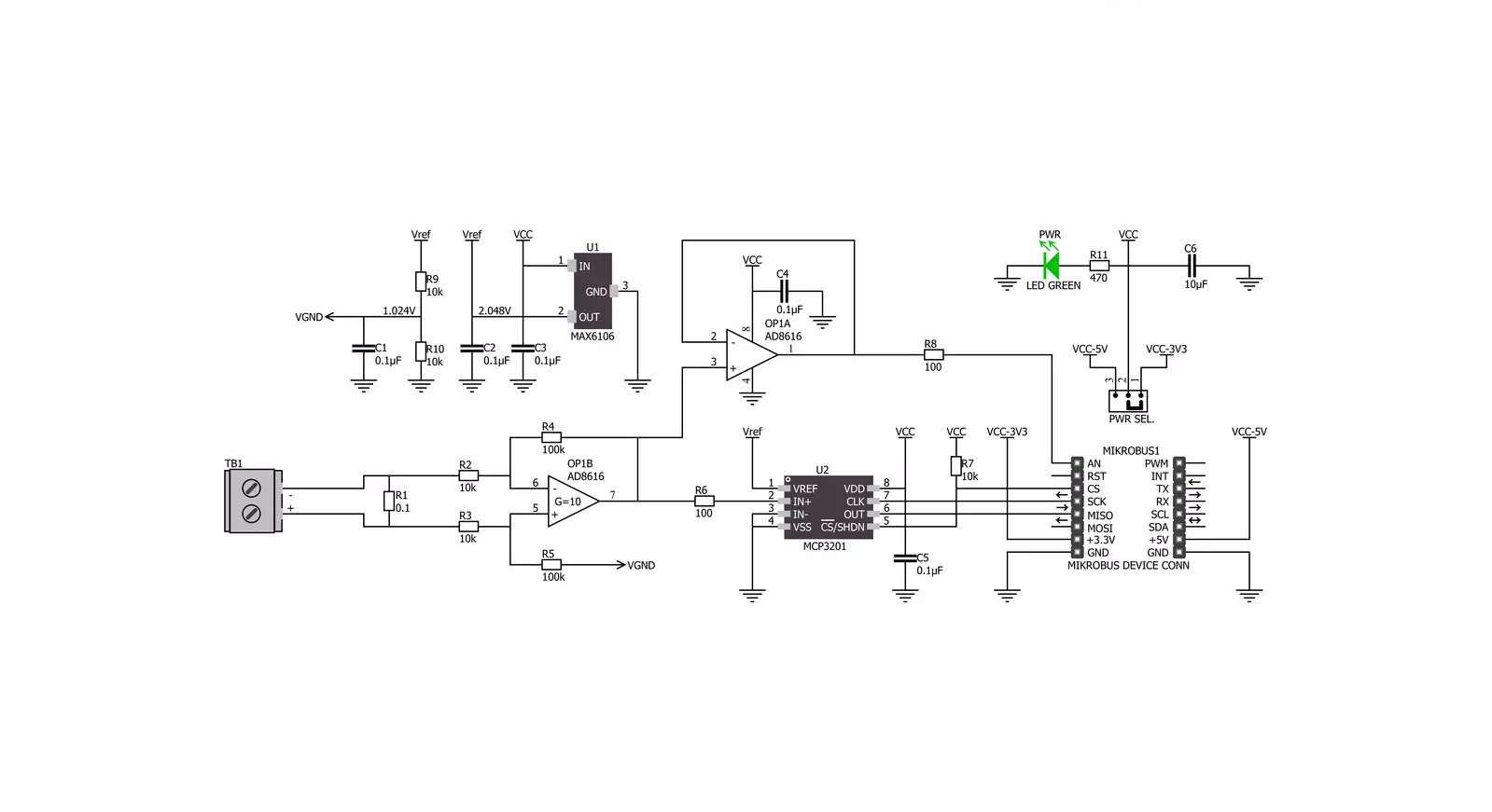
Click board™ Schematic
Step by step
Project assembly

Start by selecting your development board and Click board™. Begin with the Arduino Mega 2560 Rev3 as your development board.


Software Support
Library Description
This library contains API for Ammeter Click driver.
Key functions:
ammeter_amperage- Function is used to measure amperage of a power consumer connected to the Ammeter Click
Open Source
Code example
The complete application code and a ready-to-use project are available through the NECTO Studio Package Manager for direct installation in the NECTO Studio. The application code can also be found on the MIKROE GitHub account.
/*!
 * \file
 * \brief Ammeter Click example
 *
 * # Description
 * Demo app measures and displays current by using Ammeter Click board.
 *
 * The demo application is composed of two sections :
 *
 * ## Application Init
 * Initalizes SPI, LOG and Click drivers.
 *
 * ## Application Task
 * This is an example that shows the capabilities of the Ammeter Click by
 * measuring amperage in miliampers. Ammeter Click board can be used to saftly
 * measure current up to 1A both AC and DC, in the case of AC,
 * for peak to peak value.
 *
 * *note:*
 * It is important to notice that this Click board has its' own electronic
 * circuit, and may not be powered from the same source which we are measuring.
 * Result will not be correct in that case.
 *
 * \author Jovan Stajkovic
 *
 */
// ------------------------------------------------------------------- INCLUDES

#include "board.h"
#include "log.h"
#include "ammeter.h"

// ------------------------------------------------------------------ VARIABLES

static ammeter_t ammeter;
static log_t logger;
static float amperage;

// ------------------------------------------------------ APPLICATION FUNCTIONS

void application_init ( void )
{
    log_cfg_t log_cfg;
    ammeter_cfg_t cfg;

    /**
     * Logger initialization.
     * Default baud rate: 115200
     * Default log level: LOG_LEVEL_DEBUG
     * @note If USB_UART_RX and USB_UART_TX
     * are defined as HAL_PIN_NC, you will
     * need to define them manually for log to work.
     * See @b LOG_MAP_USB_UART macro definition for detailed explanation.
     */
    LOG_MAP_USB_UART( log_cfg );
    log_init( &logger, &log_cfg );
    log_info( &logger, "---- Application Init ----" );

    //  Click initialization.

    ammeter_cfg_setup( &cfg );
    AMMETER_MAP_MIKROBUS( cfg, MIKROBUS_1 );
    ammeter_init( &ammeter, &cfg );
    log_printf( &logger, "-----------------------\r\n" );
    log_printf( &logger, "    Ammeter  Click     \r\n" );
    log_printf( &logger, "-----------------------\r\n" );
}

void application_task ( void )
{
    amperage = ammeter_amperage( &ammeter );
    log_printf( &logger, " Current: %.2f mA\r\n", amperage );

    log_printf( &logger, "-----------------------\r\n" );
    Delay_ms ( 1000 );
}

int main ( void )
{
    /* Do not remove this line or clock might not be set correctly. */
    #ifdef PREINIT_SUPPORTED
    preinit();
    #endif

    application_init( );

    for ( ; ; )
    {
        application_task( );
    }

    return 0;
}


// ------------------------------------------------------------------------ END
Additional Support
Resources
Category:Current sensor


