Provide accurate positioning information with EVA-M8M-0 and ATmega2560
Explore with confidence: Key to the most reliable location services
Published Feb 14, 2024
Click board™
GNSS 11 Click
Dev. board
Arduino Mega 2560 Rev3
Compiler
NECTO Studio
MCU
ATmega2560
Receive signals from satellites in space to determine their precise location on Earth
A
A
Hardware Overview
How does it work?
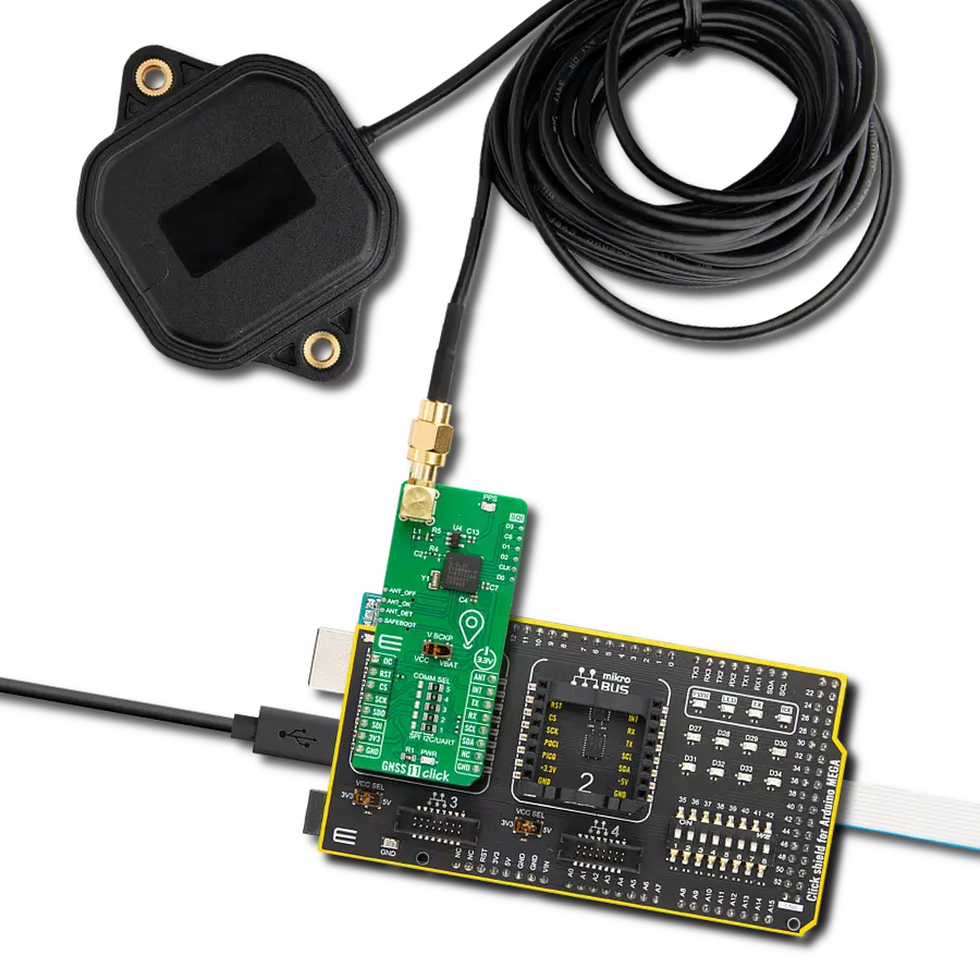
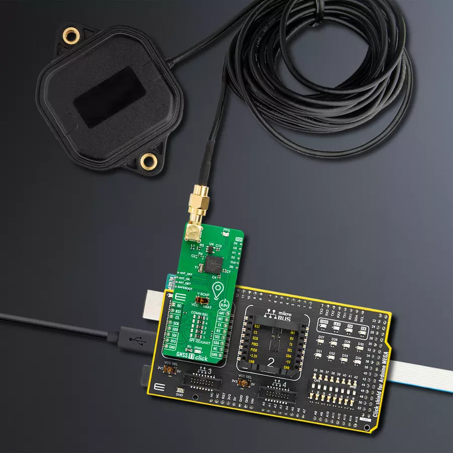
GNSS 11 Click is based on the EVA-M8M, a concurrent GNSS module from u-blox. It can process up to three GNSS and be configured for a single GNSS operation using GPS, GLONASS, or BeiDou and disable QZSS and SBAS. The module can be configured to receive any single GNSS constellation or any set of permissible combinations according to the table from the datasheet. Galileo is not enabled as the default configuration. There are several features that EVA-M8M brings to you, such as assisted GNSS (AssistNow™ online/offline/autonomous), augmentation systems (SBAS), Differential GPS, odometer, data logging, geofencing, spoofing detection, and more. GNSS 11 Click can use the SPI, I2C, or UART interface to communicate with the host MCU, which can be selected over the five COMM SEL jumpers. By default, UART and I2C are selected. The I2C is actually a DDC interface (I2C compliant) and can be operated in slave mode only, supporting a clock frequency of up to 400kHz. If you choose an SPI interface, you can count on 125kbps and 5.5MHz of clock frequency. There are several pins on the mikroBUS™ socket that you can also use. The module can be reset over the RST pin. The antenna can be turned on over the ANT pin, which enables the TPS2041B, a current-limited power distribution switch
from Texas Instruments. This switch feeds the power to an antenna, and if the output load exceeds the current-limit threshold or a short is present, the switch will limit the output current and notify the host MCU over the OC pin. The EVA-M8M module also provides an SQI interface for optional external flash for future firmware upgrades and improved A-GNSS performance. This flash can be used for the AssitNowTM Offline feature to store the orbit data, for data logging, and more. Worth mentioning is that without the external flash, only GPS satellites are used, and the prediction time decreases to three days. The SQI flash can be connected over the SQI header. This Click board™ comes equipped with a USB type C connector (2.0 FS), which can be used for communication as an alternative to the UART. In addition, thanks to the additional electronics on the board, this Click can also work in a standalone configuration, where the appropriate power supply voltage is provided by USB. The u-blox USB (CDC-ACM) driver supports Windows 7 and 8 operating systems, while for Windows 10, it is not required as it has a built-in USB serial driver. However, plugging initially into an internet-connected Windows 10 PC will download the u-blox combined sensor and VCP driver package. The interrupt INT pin can be used to control the
receiver or for aid. GNSS 11 Click possesses the SMA antenna connector with an impedance of 50Ω, which can connect the appropriate active antenna for improved range and received signal strength. The EVA-M8M module has a backup supply option on this Click board™ available as an onboard VCC input or over the coin battery. You can choose the backup source over the V BCKP switch. The time output pulse is available as a PPS LED indication. There are also several test pads on GNSS 11 Click. The EVA-M8M supports an active antenna supervisor, which enables the receiver to detect short circuits at the active antenna and antenna presence detection. The pads ANT_OFF, ANT_OK, and ANT_DET serve for testing purposes of this feature. The SAFEBOOT pad allows you to test the state of the module while entering the Safe Boot Mode, which is used for programming the flash memory in production or recovering a corrupted flash memory. This Click board™ can be operated only with a 3.3V logic voltage level. The board must perform appropriate logic voltage level conversion before using MCUs with different logic levels. Also, this Click board™ comes equipped with a library containing easy-to-use functions and an example code that can be used as a reference for further development.

Features overview
Development board
Arduino Mega 2560 is a robust microcontroller platform built around the ATmega 2560 chip. It has extensive capabilities and boasts 54 digital input/output pins, including 15 PWM outputs, 16 analog inputs, and 4 UARTs. With a 16MHz crystal
oscillator ensuring precise timing, it offers seamless connectivity via USB, a convenient power jack, an ICSP header, and a reset button. This all-inclusive board simplifies microcontroller projects; connect it to your computer via USB or power it up
using an AC-to-DC adapter or battery. Notably, the Mega 2560 maintains compatibility with a wide range of shields crafted for the Uno, Duemilanove, or Diecimila boards, ensuring versatility and ease of integration.

Microcontroller Overview
MCU Card / MCU

Architecture
AVR
MCU Memory (KB)
256
Silicon Vendor
Microchip
Pin count
100
RAM (Bytes)
8192
You complete me!
Accessories
Click Shield for Arduino Mega comes equipped with four mikroBUS™ sockets, with two in the form of a Shuttle connector, allowing all the Click board™ devices to be interfaced with the Arduino Mega board with no effort. Featuring an AVR 8-bit microcontroller with advanced RISC architecture, 54 digital I/O pins, and Arduino™ compatibility, the Arduino Mega board offers limitless possibilities for prototyping and creating diverse applications. This board is controlled and powered conveniently through a USB connection to program and debug the Arduino Mega board efficiently out of the box, with an additional USB cable connected to the USB B port on the board. Simplify your project development with the integrated ATmega16U2 programmer and unleash creativity using the extensive I/O options and expansion capabilities. There are eight switches, which you can use as inputs, and eight LEDs, which can be used as outputs of the MEGA2560. In addition, the shield features the MCP1501, a high-precision buffered voltage reference from Microchip. This reference is selected by default over the EXT REF jumper at the bottom of the board. You can choose an external one, as you would usually do with an Arduino Mega board. There is also a GND hook for testing purposes. Four additional LEDs are PWR, LED (standard pin D13), RX, and TX LEDs connected to UART1 (mikroBUS™ 1 socket). This Click Shield also has several switches that perform functions such as selecting the logic levels of analog signals on mikroBUS™ sockets and selecting logic voltage levels of the mikroBUS™ sockets themselves. Besides, the user is offered the possibility of using any Click board™ with the help of existing bidirectional level-shifting voltage translators, regardless of whether the Click board™ operates at a 3.3V or 5V logic voltage level. Once you connect the Arduino Mega board with Click Shield for Arduino Mega, you can access hundreds of Click boards™, working with 3.3V or 5V logic voltage levels.

GNSS Active External Antenna is a unique multi-band type of antenna coming from u-blox that is the perfect selection for high precision GNSS applications, which require highly accurate location abilities such as RTK. The ANN-MB-00 is a multi-band (L1, L2/E5b/B2I) active GNSS antenna with a 5m cable and SMA connector. The antenna supports GPS, GLONASS, Galileo, and BeiDou and includes a high-performance multi-band RHCP dual-feed patch antenna element, a built-in high-gain LNA with SAW pre-filtering, and a 5 m antenna cable with SMA connector, and is waterproof.

Used MCU Pins
mikroBUS™ mapper
Take a closer look
Click board™ Schematic

Step by step
Project assembly

Start by selecting your development board and Click board™. Begin with the Arduino Mega 2560 Rev3 as your development board.


Track your results in real time
Application Output
1. Application Output - In Debug mode, the 'Application Output' window enables real-time data monitoring, offering direct insight into execution results. Ensure proper data display by configuring the environment correctly using the provided tutorial.

2. UART Terminal - Use the UART Terminal to monitor data transmission via a USB to UART converter, allowing direct communication between the Click board™ and your development system. Configure the baud rate and other serial settings according to your project's requirements to ensure proper functionality. For step-by-step setup instructions, refer to the provided tutorial.

3. Plot Output - The Plot feature offers a powerful way to visualize real-time sensor data, enabling trend analysis, debugging, and comparison of multiple data points. To set it up correctly, follow the provided tutorial, which includes a step-by-step example of using the Plot feature to display Click board™ readings. To use the Plot feature in your code, use the function: plot(*insert_graph_name*, variable_name);. This is a general format, and it is up to the user to replace 'insert_graph_name' with the actual graph name and 'variable_name' with the parameter to be displayed.

Software Support
Library Description
This library contains API for GNSS 11 Click driver.
Key functions:
gnss11_reset_device- This function resets the device by toggling the RST and ANT_ON pins.gnss11_generic_read- This function reads a desired number of data bytes by using UART serial interface.gnss11_parse_gga- This function parses the GGA data from the read response buffer.
Open Source
Code example
The complete application code and a ready-to-use project are available through the NECTO Studio Package Manager for direct installation in the NECTO Studio. The application code can also be found on the MIKROE GitHub account.
/*!
 * @file main.c
 * @brief GNSS 11 Click Example.
 *
 * # Description
 * This example demonstrates the use of GNSS 11 Click by reading and displaying
 * the GNSS coordinates.
 *
 * The demo application is composed of two sections :
 *
 * ## Application Init
 * Initializes the driver and resets the Click board.
 *
 * ## Application Task
 * Reads the received data, parses the NMEA GGA info from it, and once it receives
 * the position fix it will start displaying the coordinates on the USB UART.
 *
 * ## Additional Function
 * - static void gnss11_clear_app_buf ( void )
 * - static void gnss11_log_app_buf ( void )
 * - static err_t gnss11_process ( gnss11_t *ctx )
 * - static void gnss11_parser_application ( uint8_t *rsp )
 *
 * @author Stefan Filipovic
 *
 */

#include "board.h"
#include "log.h"
#include "gnss11.h"

// Application buffer size
#define APP_BUFFER_SIZE             500
#define PROCESS_BUFFER_SIZE         200

static gnss11_t gnss11;
static log_t logger;

static uint8_t app_buf[ APP_BUFFER_SIZE ] = { 0 };
static int32_t app_buf_len = 0;

/**
 * @brief GNSS 11 clearing application buffer.
 * @details This function clears memory of application buffer and reset its length.
 * @note None.
 */
static void gnss11_clear_app_buf ( void );

/**
 * @brief GNSS 11 log application buffer.
 * @details This function logs data from application buffer to USB UART.
 * @note None.
 */
static void gnss11_log_app_buf ( void );

/**
 * @brief GNSS 11 data reading function.
 * @details This function reads data from device and concatenates data to application buffer.
 * @param[in] ctx : Click context object.
 * See #gnss11_t object definition for detailed explanation.
 * @return @li @c  0 - Read some data.
 *         @li @c -1 - Nothing is read.
 * See #err_t definition for detailed explanation.
 * @note None.
 */
static err_t gnss11_process ( gnss11_t *ctx );

/**
 * @brief GNSS 11 parser application.
 * @param[in] rsp Response buffer.
 * @details This function logs GNSS data on the USB UART.
 * @return None.
 * @note None.
 */
static void gnss11_parser_application ( uint8_t *rsp );

void application_init ( void )
{
    log_cfg_t log_cfg;  /**< Logger config object. */
    gnss11_cfg_t gnss11_cfg;  /**< Click config object. */

    /**
     * Logger initialization.
     * Default baud rate: 115200
     * Default log level: LOG_LEVEL_DEBUG
     * @note If USB_UART_RX and USB_UART_TX
     * are defined as HAL_PIN_NC, you will
     * need to define them manually for log to work.
     * See @b LOG_MAP_USB_UART macro definition for detailed explanation.
     */
    LOG_MAP_USB_UART( log_cfg );
    log_init( &logger, &log_cfg );
    log_info( &logger, " Application Init " );

    // Click initialization.
    gnss11_cfg_setup( &gnss11_cfg );
    GNSS11_MAP_MIKROBUS( gnss11_cfg, MIKROBUS_1 );
    if ( GNSS11_OK != gnss11_init( &gnss11, &gnss11_cfg ) )
    {
        log_error( &logger, " Communication init." );
        for ( ; ; );
    }

    gnss11_reset_device ( &gnss11 );
    log_info( &logger, " Application Task " );
}

void application_task ( void )
{
    gnss11_process( &gnss11 );
    if ( app_buf_len > ( sizeof ( GNSS11_RSP_GGA ) + GNSS11_GGA_ELEMENT_SIZE ) )
    {
        gnss11_parser_application( app_buf );
    }
}

int main ( void )
{
    /* Do not remove this line or clock might not be set correctly. */
    #ifdef PREINIT_SUPPORTED
    preinit();
    #endif

    application_init( );

    for ( ; ; )
    {
        application_task( );
    }

    return 0;
}

static void gnss11_clear_app_buf ( void )
{
    memset( app_buf, 0, app_buf_len );
    app_buf_len = 0;
}

static void gnss11_log_app_buf ( void )
{
    for ( int32_t buf_cnt = 0; buf_cnt < app_buf_len; buf_cnt++ )
    {
        log_printf( &logger, "%c", app_buf[ buf_cnt ] );
    }
}

static err_t gnss11_process ( gnss11_t *ctx )
{
    uint8_t rx_buf[ PROCESS_BUFFER_SIZE ] = { 0 };
    int32_t overflow_bytes = 0;
    int32_t rx_cnt = 0;
    int32_t rx_size = 0;
    if ( GNSS11_DRV_SEL_UART == ctx->drv_sel )
    {
        rx_size = gnss11_generic_read( ctx, rx_buf, PROCESS_BUFFER_SIZE );
    }
    else if ( ( GNSS11_DRV_SEL_I2C == ctx->drv_sel ) || ( GNSS11_DRV_SEL_SPI == ctx->drv_sel ) )
    {
        if ( GNSS11_OK == gnss11_generic_read( ctx, rx_buf, 1 ) )
        {
            if ( GNSS11_DUMMY != rx_buf[ 0 ] )
            {
                rx_size = 1;
            }
        }
    }
    if ( ( rx_size > 0 ) && ( rx_size <= APP_BUFFER_SIZE ) )
    {
        if ( ( app_buf_len + rx_size ) > APP_BUFFER_SIZE )
        {
            overflow_bytes = ( app_buf_len + rx_size ) - APP_BUFFER_SIZE;
            app_buf_len = APP_BUFFER_SIZE - rx_size;
            memmove ( app_buf, &app_buf[ overflow_bytes ], app_buf_len );
            memset ( &app_buf[ app_buf_len ], 0, overflow_bytes );
        }
        for ( rx_cnt = 0; rx_cnt < rx_size; rx_cnt++ )
        {
            if ( rx_buf[ rx_cnt ] )
            {
                app_buf[ app_buf_len++ ] = rx_buf[ rx_cnt ];
            }
        }
        return GNSS11_OK;
    }
    return GNSS11_ERROR;
}

static void gnss11_parser_application ( uint8_t *rsp )
{
    uint8_t element_buf[ 100 ] = { 0 };
    if ( GNSS11_OK == gnss11_parse_gga( rsp, GNSS11_GGA_LATITUDE, element_buf ) )
    {
        static uint8_t wait_for_fix_cnt = 0;
        if ( strlen( element_buf ) > 0 )
        {
            log_printf( &logger, "\r\n Latitude: %.2s degrees, %s minutes \r\n", element_buf, &element_buf[ 2 ] );
            memset( element_buf, 0, sizeof( element_buf ) );
            gnss11_parse_gga( rsp, GNSS11_GGA_LONGITUDE, element_buf );
            log_printf( &logger, " Longitude: %.3s degrees, %s minutes \r\n", element_buf, &element_buf[ 3 ] );
            memset( element_buf, 0, sizeof( element_buf ) );
            gnss11_parse_gga( rsp, GNSS11_GGA_ALTITUDE, element_buf );
            log_printf( &logger, " Altitude: %s m \r\n", element_buf );
            wait_for_fix_cnt = 0;
        }
        else
        {
            if ( wait_for_fix_cnt % 5 == 0 )
            {
                log_printf( &logger, " Waiting for the position fix...\r\n\n" );
                wait_for_fix_cnt = 0;
            }
            wait_for_fix_cnt++;
        }
        gnss11_clear_app_buf(  );
    }
}

// ------------------------------------------------------------------------ END
Additional Support
Resources
Category:GPS/GNSS


