Achieve absolute pressure and temperature measurement in demanding environments with MS5849-07BA and ATmega2560
Chlorine resistant pressure sensing solution for altimetry and mid pressure measurement

Published Aug 07, 2024
Click board™
Pressure 23 Click - 07BA
Dev. board
Arduino Mega 2560 Rev3
Compiler
NECTO Studio
MCU
ATmega2560
Provide accurate pressure and temperature data for engine management systems, tire pressure monitoring, and other automotive systems
A
A
Hardware Overview
How does it work?
Pressure 23 Click - 07BA is based on the MS5849-07BA, an ultra-compact, chlorine-resistant absolute pressure sensor developed by TE Connectivity. This high-performance sensor delivers precise absolute pressure measurements with a 24-bit resolution and transmits the data digitally via I2C or SPI interfaces. It is engineered to operate within pressure ranges from 0.4 to 7 bar and features a media-protected design with a chlorine-resistant gel coating, making it ideal for harsh environments. Additionally, it measures temperature over a wide range from -20 to +85°C and makes an excellent choice for applications requiring reliable and precise pressure and temperature measurements in challenging environments. The MS5849-07BA sensor combines a piezoresistive pressure cell with an amplifier A/D interface IC, all enclosed in a
robust QFN package. This package includes a grounded metal ring that shields the electronic components and facilitates secure O-ring mounting. The sensor processes the measured pressure and temperature signals, converting them into a 24-bit data word. It also stores six unique coefficients that enable highly accurate software correction for both pressure and temperature measurements when processed by a host microcontroller unit (MCU). As mentioned, Pressure 23 Click - 07BA can communicate with the host MCU using the 4-Wire SPI serial interface and the I2C interface. The SPI interface supports clock frequencies up to 10MHz, while the I2C clock supports up to 3.4MHz. The desired communication interface can be chosen over the 5 COMM SEL jumpers, where the SPI is set by default. If your goal is the I2C, you can
select the I2C address over the ADDR SEL jumper (0 set by default). The chosen communication interface provides flexibility in configuring the oversampling rate and optimizing both speed and power consumption based on application requirements. Besides communication pins, this board also uses an interrupt INT pin, which will be raised for different conditions, such as pressure and temperature thresholds, finished ADC conversion, and more. This Click board™ can be operated only with a 3.3V logic voltage level. The board must perform appropriate logic voltage level conversion before using MCUs with different logic levels. Also, it comes equipped with a library containing functions and an example code that can be used as a reference for further development.

Features overview
Development board
Arduino Mega 2560 is a robust microcontroller platform built around the ATmega 2560 chip. It has extensive capabilities and boasts 54 digital input/output pins, including 15 PWM outputs, 16 analog inputs, and 4 UARTs. With a 16MHz crystal
oscillator ensuring precise timing, it offers seamless connectivity via USB, a convenient power jack, an ICSP header, and a reset button. This all-inclusive board simplifies microcontroller projects; connect it to your computer via USB or power it up
using an AC-to-DC adapter or battery. Notably, the Mega 2560 maintains compatibility with a wide range of shields crafted for the Uno, Duemilanove, or Diecimila boards, ensuring versatility and ease of integration.

Microcontroller Overview
MCU Card / MCU

Architecture
AVR
MCU Memory (KB)
256
Silicon Vendor
Microchip
Pin count
100
RAM (Bytes)
8192
You complete me!
Accessories
Click Shield for Arduino Mega comes equipped with four mikroBUS™ sockets, with two in the form of a Shuttle connector, allowing all the Click board™ devices to be interfaced with the Arduino Mega board with no effort. Featuring an AVR 8-bit microcontroller with advanced RISC architecture, 54 digital I/O pins, and Arduino™ compatibility, the Arduino Mega board offers limitless possibilities for prototyping and creating diverse applications. This board is controlled and powered conveniently through a USB connection to program and debug the Arduino Mega board efficiently out of the box, with an additional USB cable connected to the USB B port on the board. Simplify your project development with the integrated ATmega16U2 programmer and unleash creativity using the extensive I/O options and expansion capabilities. There are eight switches, which you can use as inputs, and eight LEDs, which can be used as outputs of the MEGA2560. In addition, the shield features the MCP1501, a high-precision buffered voltage reference from Microchip. This reference is selected by default over the EXT REF jumper at the bottom of the board. You can choose an external one, as you would usually do with an Arduino Mega board. There is also a GND hook for testing purposes. Four additional LEDs are PWR, LED (standard pin D13), RX, and TX LEDs connected to UART1 (mikroBUS™ 1 socket). This Click Shield also has several switches that perform functions such as selecting the logic levels of analog signals on mikroBUS™ sockets and selecting logic voltage levels of the mikroBUS™ sockets themselves. Besides, the user is offered the possibility of using any Click board™ with the help of existing bidirectional level-shifting voltage translators, regardless of whether the Click board™ operates at a 3.3V or 5V logic voltage level. Once you connect the Arduino Mega board with Click Shield for Arduino Mega, you can access hundreds of Click boards™, working with 3.3V or 5V logic voltage levels.

Used MCU Pins
mikroBUS™ mapper
Take a closer look
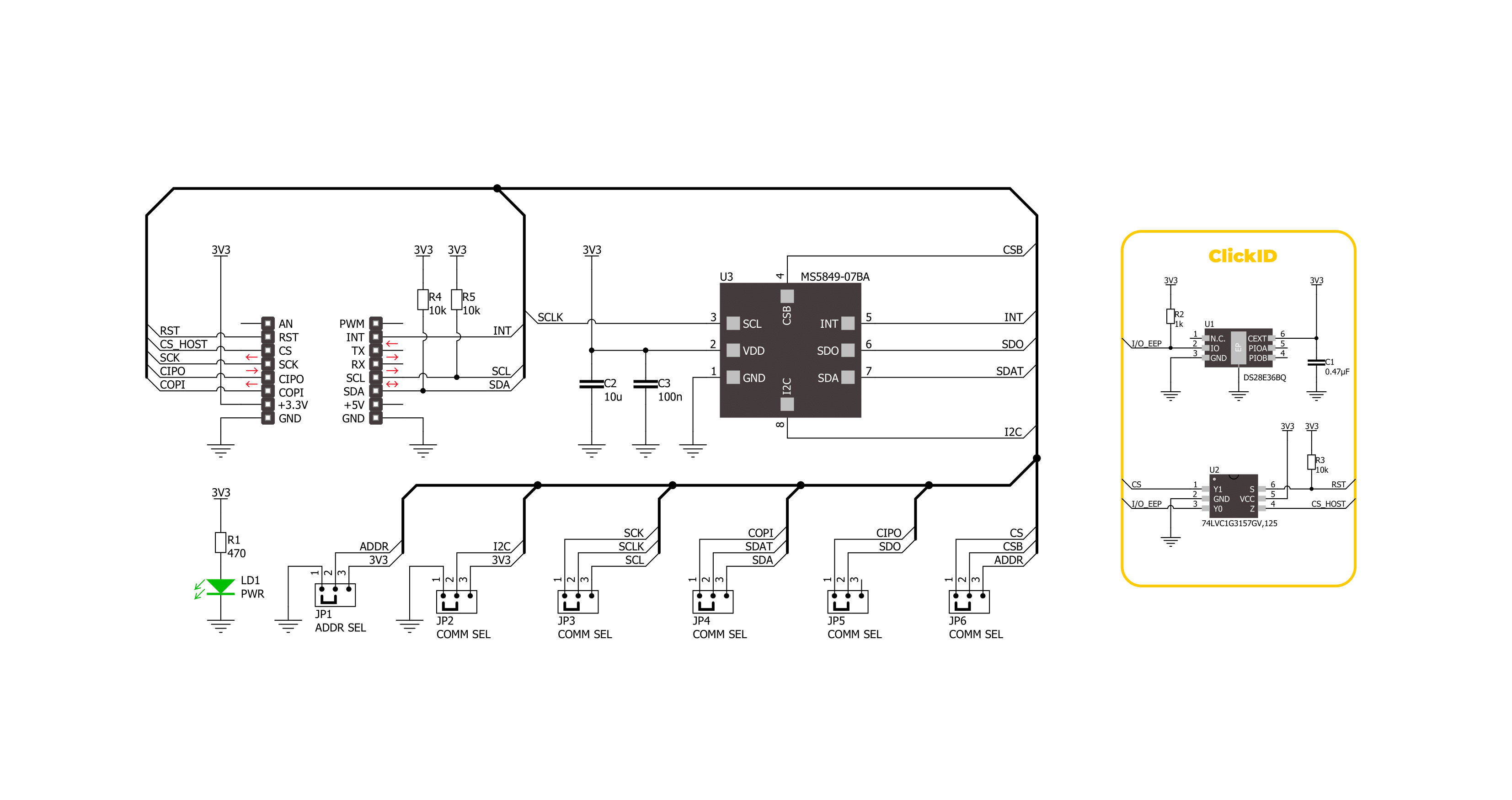
Click board™ Schematic
Step by step
Project assembly

Start by selecting your development board and Click board™. Begin with the Arduino Mega 2560 Rev3 as your development board.


Software Support
Library Description
This library contains API for Pressure 23 Click - 07BA driver.
Key functions:
pressure2307ba_get_measurement_data- Pressure 23 07BA gets the measurement data function.pressure2307ba_get_calibration_data- Pressure 23 07BA gets the calibration data function.pressure2307ba_read_adc- Pressure 23 07BA ADC data reading function.
Open Source
Code example
The complete application code and a ready-to-use project are available through the NECTO Studio Package Manager for direct installation in the NECTO Studio. The application code can also be found on the MIKROE GitHub account.
/*!
 * @file main.c
 * @brief Pressure 23 07BA Click example
 *
 * # Description
 * This example demonstrates the use of Pressure 23 07BA Click board by reading and displaying
 * the pressure and temperature measurements.
 *
 * The demo application is composed of two sections :
 *
 * ## Application Init
 * The initialization of I2C or SPI module and log UART.
 * After driver initialization, the app sets the default configuration.
 *
 * ## Application Task
 * The demo application reads and displays the Pressure [mBar]
 * and Temperature [degree Celsius] data.
 * Results are being sent to the UART Terminal, where you can track their changes.
 *
 * @author MikroE Team
 *
 */

#include "board.h"
#include "log.h"
#include "pressure2307ba.h"

static pressure2307ba_t pressure2307ba;
static log_t logger;

void application_init ( void )
{
    log_cfg_t log_cfg;  /**< Logger config object. */
    pressure2307ba_cfg_t pressure2307ba_cfg;  /**< Click config object. */

    /**
     * Logger initialization.
     * Default baud rate: 115200
     * Default log level: LOG_LEVEL_DEBUG
     * @note If USB_UART_RX and USB_UART_TX
     * are defined as HAL_PIN_NC, you will
     * need to define them manually for log to work.
     * See @b LOG_MAP_USB_UART macro definition for detailed explanation.
     */
    LOG_MAP_USB_UART( log_cfg );
    log_init( &logger, &log_cfg );
    log_info( &logger, " Application Init " );

    // Click initialization.
    pressure2307ba_cfg_setup( &pressure2307ba_cfg );
    PRESSURE2307BA_MAP_MIKROBUS( pressure2307ba_cfg, MIKROBUS_1 );
    err_t init_flag = pressure2307ba_init( &pressure2307ba, &pressure2307ba_cfg );
    if ( ( I2C_MASTER_ERROR == init_flag ) || ( SPI_MASTER_ERROR == init_flag ) )
    {
        log_error( &logger, " Communication init." );
        for ( ; ; );
    }

    if ( PRESSURE2307BA_ERROR == pressure2307ba_default_cfg ( &pressure2307ba ) )
    {
        log_error( &logger, " Default configuration." );
        for ( ; ; );
    }

    log_info( &logger, " Application Task " );
    log_printf( &logger, " _______________________ \r\n" );
    Delay_ms ( 100 );
}

void application_task ( void )
{
    static float temperature, pressure;
    if ( PRESSURE2307BA_OK == pressure2307ba_get_measurement_data( &pressure2307ba, &pressure, &temperature ) )
    {
        log_printf( &logger, " Pressure    : %.2f mBar \r\n", pressure );
        log_printf( &logger, " Temperature : %.2f degC \r\n", temperature );
        log_printf( &logger, " _______________________ \r\n" );
        Delay_ms ( 1000 );
    }
}

int main ( void )
{
    /* Do not remove this line or clock might not be set correctly. */
    #ifdef PREINIT_SUPPORTED
    preinit();
    #endif

    application_init( );

    for ( ; ; )
    {
        application_task( );
    }

    return 0;
}

// ------------------------------------------------------------------------ END
Additional Support
Resources
Category:Pressure


