Monitor and assess the levels of pollutants with MQ-135 and PIC24FV16KA301
Your trusted ally in the pursuit of purer air

Published Nov 01, 2023
Click board™
Air quality Click
Dev. board
EasyPIC v8 for PIC24/dsPIC33
Compiler
NECTO Studio
MCU
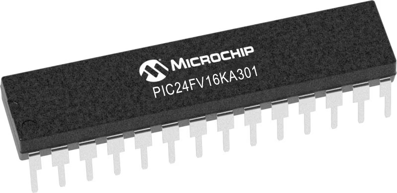
PIC24FV16KA301
By providing real-time monitoring and analysis of air pollutants, this air quality solution aims to protect human health and well-being, reducing the risk of respiratory issues, allergies, and other adverse health effects associated with poor air quality
A
A
Hardware Overview
How does it work?
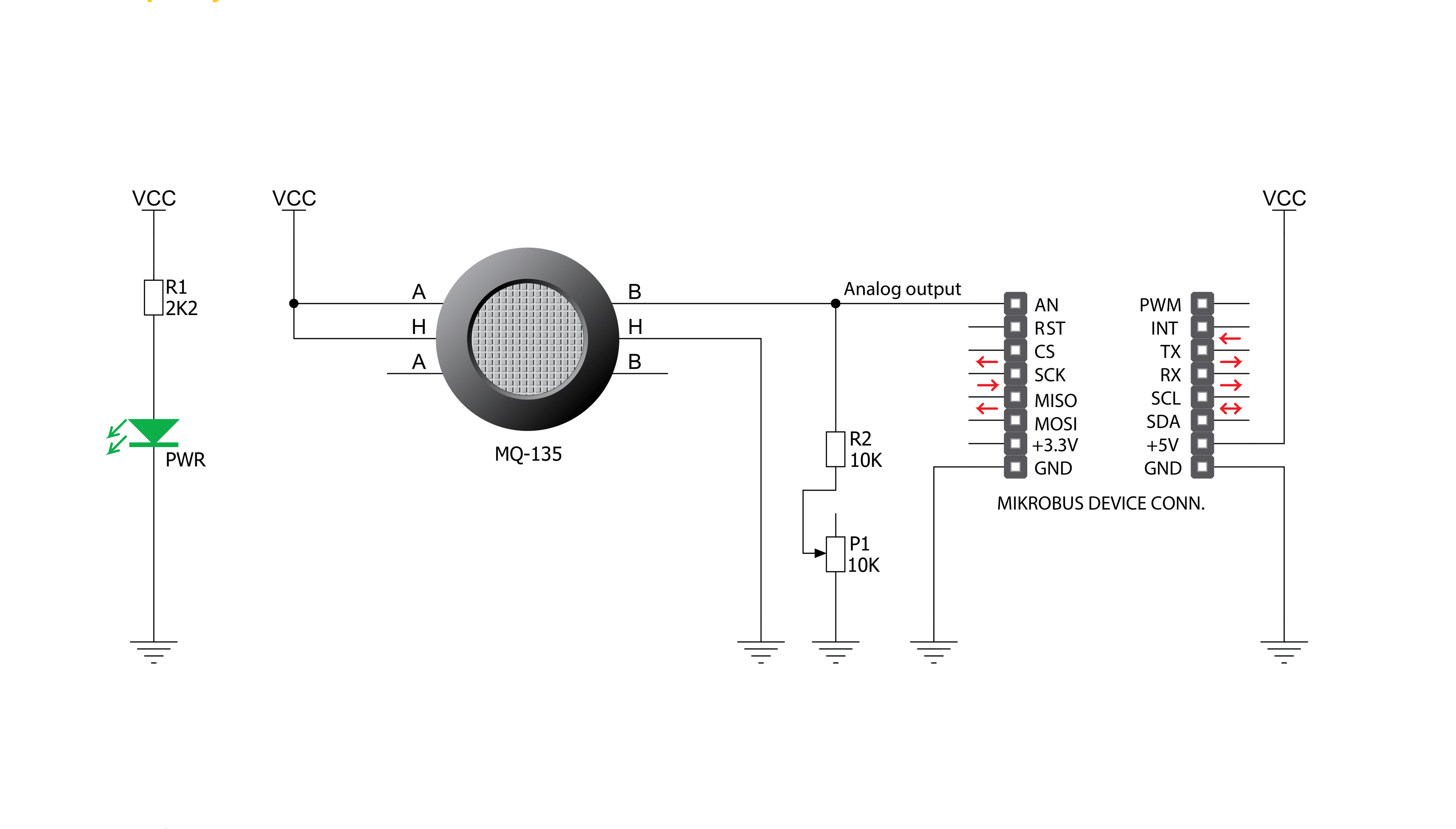
Air Quality Click is based on the MQ-135, an air quality sensor module for poisonous gases from Zhengzhou Winsen Electronics Technology. The MQ-135 can detect the presence and concentration of toxic gases in the air, such as ammonia gas, sulfide, and benzene steam. It consists of a tin dioxide sensitive layer (SnO2) inside an aluminum oxide AL2O3 ceramic tube (measuring electrodes) alongside a heating element inside its tubular casing. The heater is fixed into a plastic and stainless steel net crust, providing necessary work
conditions for sensitive components. Besides its high sensitivity, the MQ-135 is also characterized by a detection range from 10 to 1000ppm for ammonia gas, toluene, hydrogen, and smoke. The MQ-3 provides an analog representation of polluted concentration in the air sent directly to an analog pin of the mikroBUS™ socket labeled OUT. The analog output voltage the sensor provides varies in proportion to the toxic gas concentration; the higher the toxic gas concentration in the air, the higher the output voltage. Also, this Click board™ has a
built-in potentiometer that allows users to adjust the load resistance of the MQ-135 circuit for optimum performance. This Click board™ can be operated only with a 5V logic voltage level. The board must perform appropriate logic voltage level conversion before using MCUs with different logic levels. However, the Click board™ comes equipped with a library containing functions and an example code that can be used, as a reference, for further development.

Features overview
Development board
EasyPIC v8 for PIC24/dsPIC33 is a development board specially designed for the needs of rapid development of embedded applications. It supports a wide range of 16-bit PIC24/dsPIC33 microcontrollers from Microchip and has a broad set of unique functions, such as the first-ever embedded debugger/programmer. The development board is well organized and designed so that the end-user has all the necessary elements, such as switches, buttons, indicators, connectors, and others, in one place. Thanks to innovative manufacturing technology, EasyPIC v8 for PIC24/dsPIC33 provides a fluid and immersive working experience, allowing access anywhere and under any circumstances. Each part of the EasyPIC
v8 for PIC24/dsPIC33 development board contains the components necessary for the most efficient operation of the same board. In addition to the advanced integrated CODEGRIP programmer/debugger module, which offers many valuable programming/debugging options and seamless integration with the Mikroe software environment, the board also includes a clean and regulated power supply module for the development board. It can use a wide range of external power sources, including a battery, an external 12V power supply, and a power source via the USB Type-C (USB-C) connector. Communication options such as USB HOST/DEVICE, USB-UART, CAN, and LIN are also
included, including the well-established mikroBUS™ standard, two display options (graphical and character-based LCD), and several different DIP sockets. These sockets cover a wide range of 16-bit PIC24/dsPIC33 MCUs, from the smallest PIC24/dsPIC33 MCUs with only 14 up to 28 pins. EasyPIC v8 for PIC24/dsPIC33 is an integral part of the Mikroe ecosystem for rapid development. Natively supported by Mikroe software tools, it covers many aspects of prototyping and development thanks to a considerable number of different Click boards™ (over a thousand boards), the number of which is growing every day.

Microcontroller Overview
MCU Card / MCU
Architecture
dsPIC
MCU Memory (KB)
16
Silicon Vendor
Microchip
Pin count
28
RAM (Bytes)
2048
Used MCU Pins
mikroBUS™ mapper
Take a closer look
Click board™ Schematic
Step by step
Project assembly

Start by selecting your development board and Click board™. Begin with the EasyPIC v8 for PIC24/dsPIC33 as your development board.


Software Support
Library Description
This library contains API for Air Quality Click driver.
Key functions:
airquality_read_an_pin_value- This function reads results of AD conversion of the AN pinairquality_read_an_pin_voltage- This function reads results of AD conversion of the AN pin and converts them to proportional voltage level
Open Source
Code example
The complete application code and a ready-to-use project are available through the NECTO Studio Package Manager for direct installation in the NECTO Studio. The application code can also be found on the MIKROE GitHub account.
/*!
 * @file main.c
 * @brief Air quality Click Example.
 *
 * # Description
 * The demo application shows the reading of the adc
 * values given by the sensors.
 *
 * The demo application is composed of two sections :
 *
 * ## Application Init
 * Configuring Clicks and log objects.
 *
 * ## Application Task
 * Reads the adc value and prints in two forms (DEC and HEX).
 *
 * @author Jelena Milosavljevic
 *
 */
// ------------------------------------------------------------------- INCLUDES
#include "board.h"
#include "log.h"
#include "airquality.h"

// ------------------------------------------------------------------ VARIABLES

static airquality_t airquality;   /**< Air quality Click driver object. */
static log_t logger;    /**< Logger object. */

void application_init ( void ) {
    log_cfg_t log_cfg;  /**< Logger config object. */
    airquality_cfg_t airquality_cfg;  /**< Click config object. */

    /**
     * Logger initialization.
     * Default baud rate: 115200
     * Default log level: LOG_LEVEL_DEBUG
     * @note If USB_UART_RX and USB_UART_TX
     * are defined as HAL_PIN_NC, you will
     * need to define them manually for log to work.
     * See @b LOG_MAP_USB_UART macro definition for detailed explanation.
     */
    LOG_MAP_USB_UART( log_cfg );
    log_init( &logger, &log_cfg );
    log_info( &logger, " Application Init " );

    // Click initialization.

    airquality_cfg_setup( &airquality_cfg );
    AIRQUALITY_MAP_MIKROBUS( airquality_cfg, MIKROBUS_1 );
    if ( airquality_init( &airquality, &airquality_cfg ) == ADC_ERROR ) {
        log_error( &logger, " Application Init Error. " );
        log_info( &logger, " Please, run program again... " );

        for ( ; ; );
    }
    log_info( &logger, " Application Task " );
}

void application_task ( void ) {
    uint16_t airquality_an_value = 0;

    if ( airquality_read_an_pin_value ( &airquality, &airquality_an_value ) != ADC_ERROR ) {
        log_printf( &logger, " ADC Value : %u\r\n", airquality_an_value );
    }

    float airquality_an_voltage = 0;

    if ( airquality_read_an_pin_voltage ( &airquality, &airquality_an_voltage ) != ADC_ERROR ) {
        log_printf( &logger, " AN Voltage : %.3f[V]\r\n\n", airquality_an_voltage );
    }

    Delay_ms ( 1000 );
}

int main ( void )
{
    /* Do not remove this line or clock might not be set correctly. */
    #ifdef PREINIT_SUPPORTED
    preinit();
    #endif

    application_init( );

    for ( ; ; )
    {
        application_task( );
    }

    return 0;
}

// ------------------------------------------------------------------------ END
Additional Support
Resources
Category:Gas


