Build your BLDC motor driver with DRV8313 and STM32F407VGT6
A smoother drive starts with us!
Published Feb 14, 2024
Click board™
Brushless 20 Click
Dev. board
Discovery kit with STM32F407VG MCU
Compiler
NECTO Studio
MCU
STM32F407VGT6
3-phase motor driver for BLDC motor control, solenoids, or other loads
A
A
Hardware Overview
How does it work?
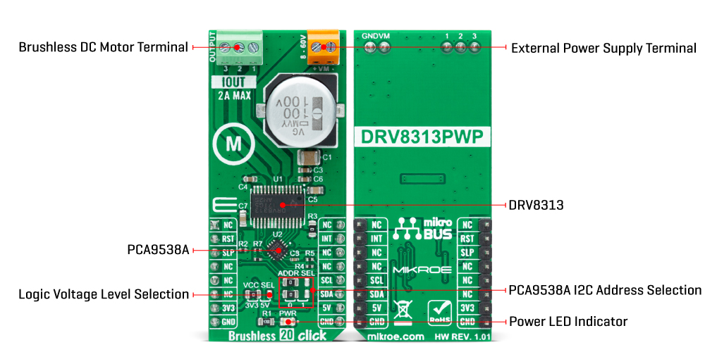
Brushless 20 Click is based on the DRV8313, a fully integrated three-phase BLDC motor driver from Texas Instruments. The highly integrated DRV8313 comes with PWM/enable control interface, a wide voltage operating range, an integrated 10mA LDO, and robust on-chip protection features. Low RDSON and efficient switching algorithms ensure excellent thermal performance and high drive capability. This Click board™ offers an energy-saving solution and quiet motor operation for brushless DC (BLDC) motors used in various applications. Each output driver channel comprises N-channel power MOSFETs configured in a 1/2-H-bridge configuration. Control pins can be accessed through the I2C interface
and the PCA9538A port expander, with which the states of those pins, alongside the state of the output terminals, can be directly controlled. The PCA9538A also allows choosing the least significant bit (LSB) of its I2C slave address by positioning SMD jumpers labeled ADDR SEL to an appropriate position marked as 0 and 1, alongside its interrupt and Reset features routed to the INT and RST pins of the mikroBUS™ socket. The DRV8313 is active unless the SLP pin, routed to the CS pin of the mikroBUS™ socket, is brought to a low logic state. The charge pump and output FETs are disabled in sleep mode alongside the internal LDO regulator. The DRV313 is automatically brought out of sleep mode if SLP is in a logic high state.
This board also supports an external power supply for the motor, which can be connected to the input terminal labeled as VM and should be within the range of 8V to 60V, while the BLDC motor coils can be connected to the terminals labeled as 1, 2, and 3. This Click board™ can operate with either 3.3V or 5V logic voltage levels selected via the VCC SEL jumper. This way, both 3.3V and 5V capable MCUs can use the communication lines properly. However, the Click board™ comes equipped with a library containing easy-to-use functions and an example code that can be used, as a reference, for further development.
Features overview
Development board
Discovery kit with STM32F407VG MCU, powered by the STM32F407 microcontroller, simplifies audio application development. It offers a robust platform with features like the ST-LINK/V2-A debugger, STMEMS digital accelerometer, digital microphone, and integrated audio DAC with a class D speaker driver. It has LEDs, push buttons, and a USB OTG
Micro-AB connector for versatile connectivity. The STM32F407VGT6 MCU boasts a 32-bit Arm Cortex-M4 with FPU, 1MB Flash memory, and 192KB RAM, housed in an LQFP100 package. Equipped with USB OTG FS, MEMS accelerometer, omnidirectional digital microphone, and user-friendly buttons, it ensures seamless operation.
The board accommodates various add-ons via extension headers while offering flexible power supply options, including ST-LINK, USB VBUS, or external sources. Supported by comprehensive free software and a range of IDEs, it empowers developers with flexibility and ease of use, making it an ideal choice for audio-centric projects.

Microcontroller Overview
MCU Card / MCU

Architecture
ARM Cortex-M4
MCU Memory (KB)
10
Silicon Vendor
STMicroelectronics
Pin count
100
RAM (Bytes)
100
You complete me!
Accessories
STM32F4 Discovery Shield is the perfect extension for your STM32F4 Discovery Board from STMicroelectronics. This versatile shield features four mikroBUS™ host sockets, a USB-UART module, and a CAN transceiver, expanding the capabilities of your Discovery board. Acting as a docking station, the STM32F4 Discovery Shield enables you to effortlessly transform your board into various applications, whether it's an RFID lock, SMS-triggered control switch, GPS tracking device, full-blown weather station, or any other idea you have in mind. With its seamless integration and enhanced functionality, this shield empowers you to explore endless possibilities and quickly bring your projects to life.

Brushless DC (BLDC) Motor with a Hall sensor represents a high-performance motor from the 42BLF motor series. This motor, wired in a star configuration, boasts a Hall Effect angle of 120°, ensuring precise and reliable performance. With a compact motor length of 47mm and a lightweight design tipping the scales at just 0.29kg, this BLDC motor is engineered to meet your needs. Operating flawlessly at a voltage rating of 24VDC and a speed range of 4000 ± 10% RPM, this motor offers consistent and dependable power. It excels in a normal operational temperature range from -20 to +50°C, maintaining efficiency with a rated current of 1.9A. Also, this product seamlessly integrates with all Brushless Click boards™ and those that require BLDC motors with Hall sensors.

Used MCU Pins
mikroBUS™ mapper
Take a closer look
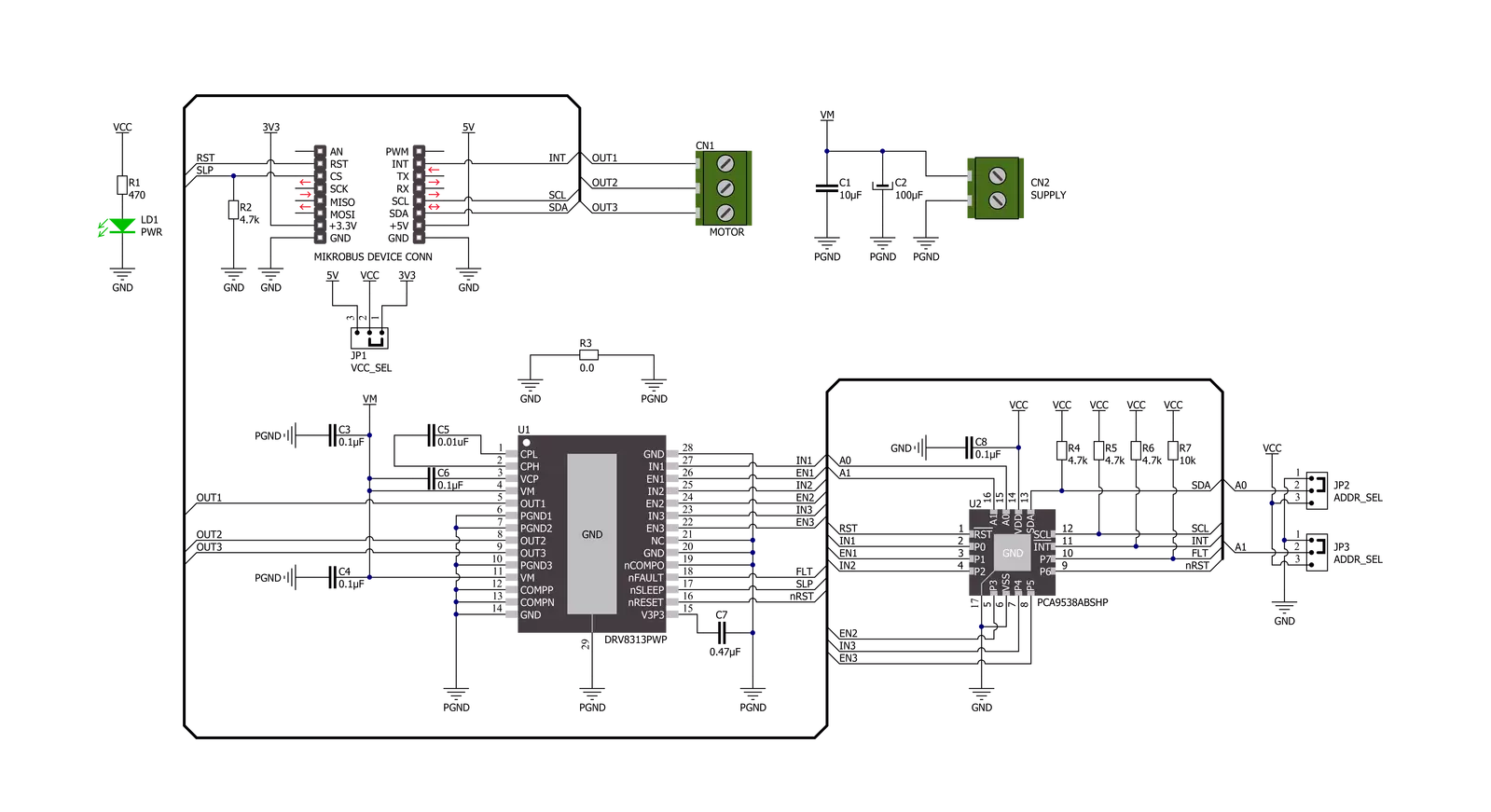
Click board™ Schematic
Step by step
Project assembly

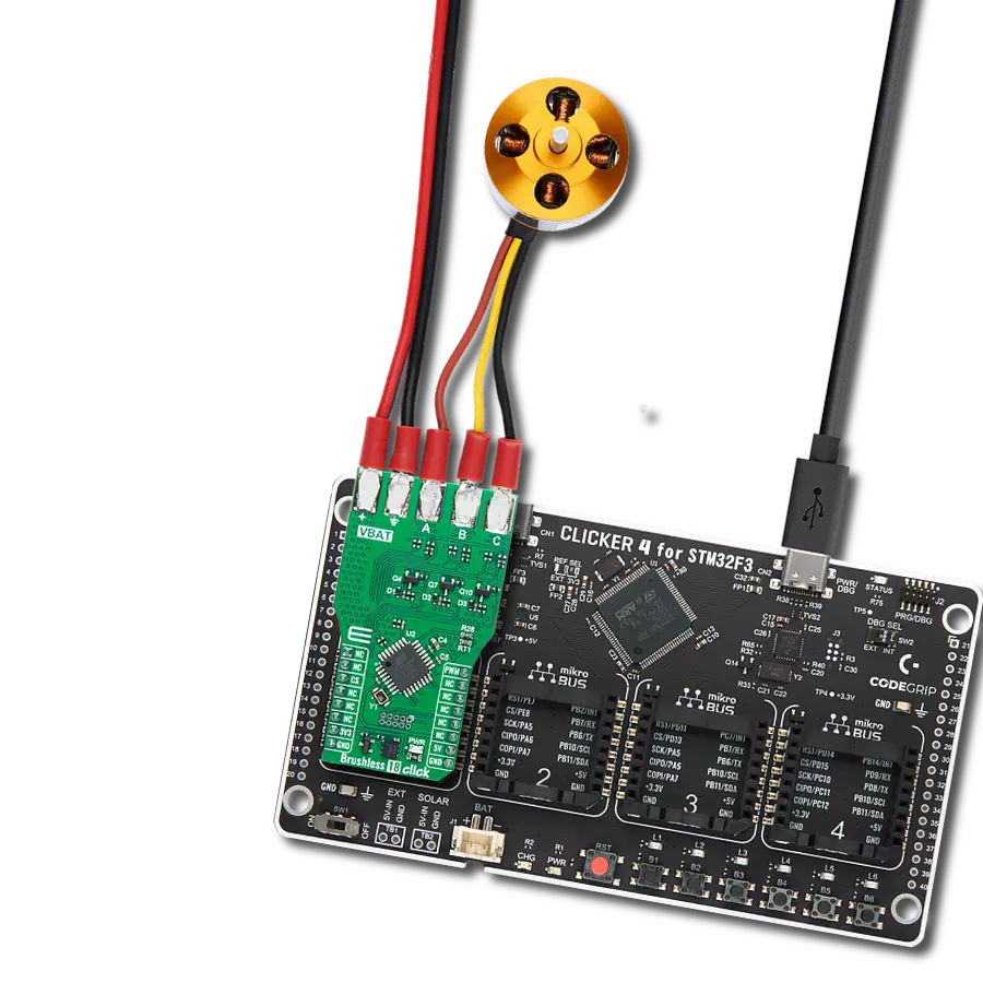
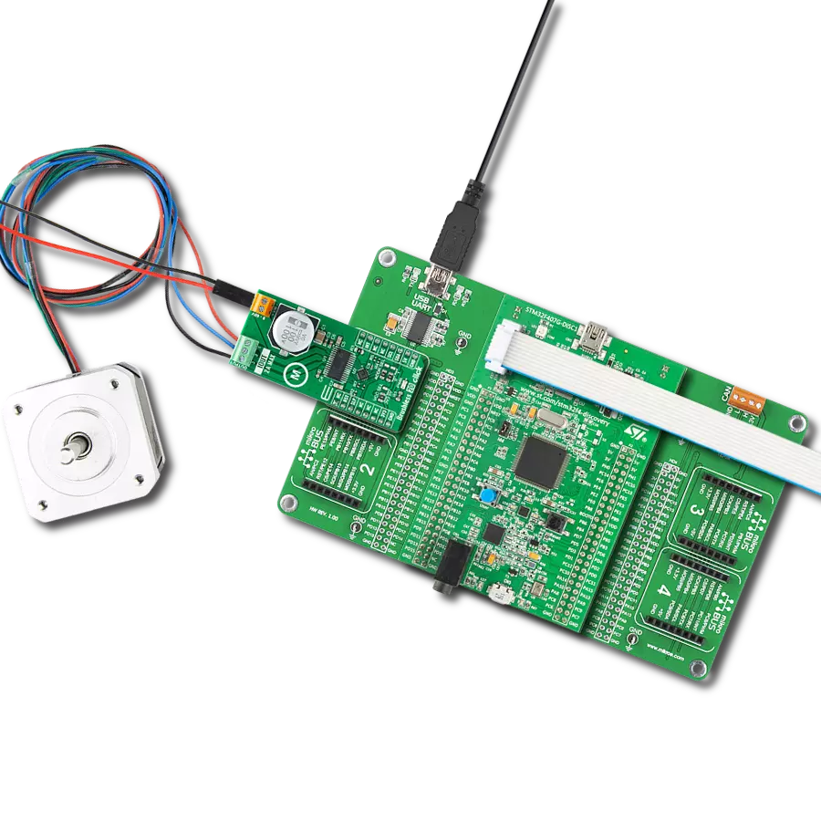
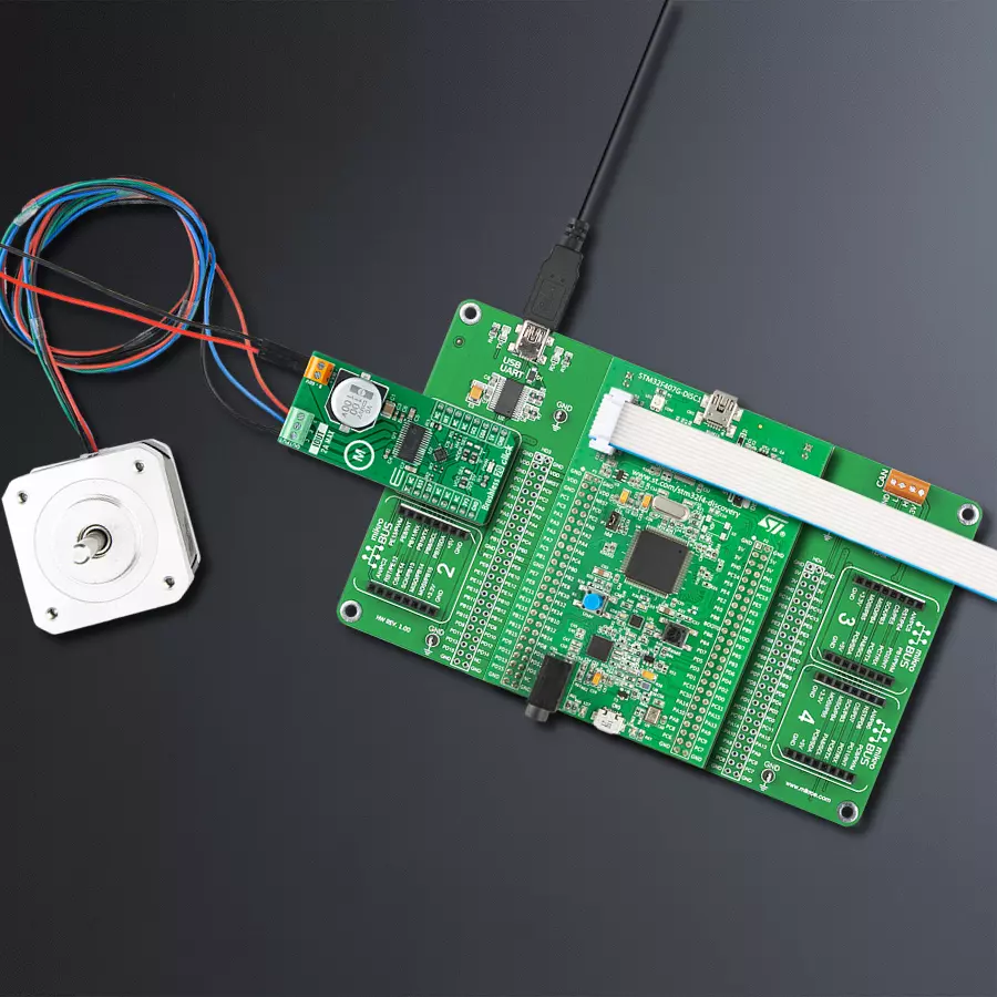
Start by selecting your development board and Click board™. Begin with the Discovery kit with STM32F407VG MCU as your development board.


Track your results in real time
Application Output
1. Application Output - In Debug mode, the 'Application Output' window enables real-time data monitoring, offering direct insight into execution results. Ensure proper data display by configuring the environment correctly using the provided tutorial.

2. UART Terminal - Use the UART Terminal to monitor data transmission via a USB to UART converter, allowing direct communication between the Click board™ and your development system. Configure the baud rate and other serial settings according to your project's requirements to ensure proper functionality. For step-by-step setup instructions, refer to the provided tutorial.

3. Plot Output - The Plot feature offers a powerful way to visualize real-time sensor data, enabling trend analysis, debugging, and comparison of multiple data points. To set it up correctly, follow the provided tutorial, which includes a step-by-step example of using the Plot feature to display Click board™ readings. To use the Plot feature in your code, use the function: plot(*insert_graph_name*, variable_name);. This is a general format, and it is up to the user to replace 'insert_graph_name' with the actual graph name and 'variable_name' with the parameter to be displayed.

Software Support
Library Description
This library contains API for Brushless 20 Click driver.
Key functions:
brushless20_perform_com_sequenceThis function performs a single commutation sequence at a desired speed for the selected rotation direction.brushless20_drive_motorThis function drives the motor for a desired time by performing multiple commutation sequences for the selected rotation direction at a desired speed.brushless20_get_fault_pinThis function returns the fault pin logic state.
Open Source
Code example
The complete application code and a ready-to-use project are available through the NECTO Studio Package Manager for direct installation in the NECTO Studio. The application code can also be found on the MIKROE GitHub account.
/*!
 * @file main.c
 * @brief Brushless 20 Click example
 *
 * # Description
 * This example demonstrates the use of the Brushless 20 Click board by driving the
 * motor in both directions at different speeds.
 *
 * The demo application is composed of two sections :
 *
 * ## Application Init
 * Initializes the driver and performs the Click default configuration.
 *
 * ## Application Task
 * Drives the motor in both directions and changes the motor speed every 3 seconds approximately.
 * The current driving direction and speed will be displayed on the USB UART.
 *
 * @author Stefan Filipovic
 *
 */

#include "board.h"
#include "log.h"
#include "brushless20.h"

static brushless20_t brushless20;
static log_t logger;

void application_init ( void )
{
    log_cfg_t log_cfg;  /**< Logger config object. */
    brushless20_cfg_t brushless20_cfg;  /**< Click config object. */

    /**
     * Logger initialization.
     * Default baud rate: 115200
     * Default log level: LOG_LEVEL_DEBUG
     * @note If USB_UART_RX and USB_UART_TX
     * are defined as HAL_PIN_NC, you will
     * need to define them manually for log to work.
     * See @b LOG_MAP_USB_UART macro definition for detailed explanation.
     */
    LOG_MAP_USB_UART( log_cfg );
    log_init( &logger, &log_cfg );
    log_info( &logger, " Application Init " );

    // Click initialization.
    brushless20_cfg_setup( &brushless20_cfg );
    BRUSHLESS20_MAP_MIKROBUS( brushless20_cfg, MIKROBUS_1 );
    if ( I2C_MASTER_ERROR == brushless20_init( &brushless20, &brushless20_cfg ) )
    {
        log_error( &logger, " Communication init." );
        for ( ; ; );
    }

    if ( BRUSHLESS20_ERROR == brushless20_default_cfg ( &brushless20 ) )
    {
        log_error( &logger, " Default configuration." );
        for ( ; ; );
    }

    log_info( &logger, " Application Task " );
}

void application_task ( void )
{
    log_printf ( &logger, "\r\n Driving motor clockwise \r\n" );
    for ( uint8_t speed = BRUSHLESS20_SPEED_MIN; speed <= BRUSHLESS20_SPEED_MAX; speed += 20 )
    {
        log_printf ( &logger, " Speed: %u\r\n", ( uint16_t ) speed );
        if ( BRUSHLESS20_OK != brushless20_drive_motor ( &brushless20, BRUSHLESS20_DIR_CW, speed, 3000 ) )
        {
            log_error ( &logger, " Drive motor " );
        }
    }
    Delay_ms ( 1000 );
    log_printf ( &logger, "\r\n Driving motor counter-clockwise \r\n" );
    for ( uint8_t speed = BRUSHLESS20_SPEED_MIN; speed <= BRUSHLESS20_SPEED_MAX; speed += 20 )
    {
        log_printf ( &logger, " Speed: %u\r\n", ( uint16_t ) speed );
        if ( BRUSHLESS20_OK != brushless20_drive_motor ( &brushless20, BRUSHLESS20_DIR_CCW, speed, 3000 ) )
        {
            log_error ( &logger, " Drive motor " );
        }
    }
    Delay_ms ( 1000 );
}

int main ( void )
{
    /* Do not remove this line or clock might not be set correctly. */
    #ifdef PREINIT_SUPPORTED
    preinit();
    #endif

    application_init( );

    for ( ; ; )
    {
        application_task( );
    }

    return 0;
}

// ------------------------------------------------------------------------ END
Additional Support
Resources
Category:Brushless