Deliver measurements of current, voltage, power, and temperature with the TSC1641 and STM32F407VGT6
Digital power monitor for alerting undesirable operating conditions
Published Jun 06, 2024
Click board™
Current 12 Click
Dev. board
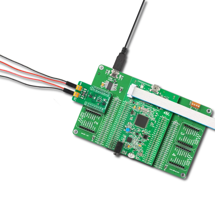
Discovery kit with STM32F407VG MCU
Compiler
NECTO Studio
MCU
STM32F407VGT6
Achieve precise regulation and monitoring of voltage, current, and power ensuring stable and reliable power delivery
A
A
Hardware Overview
How does it work?
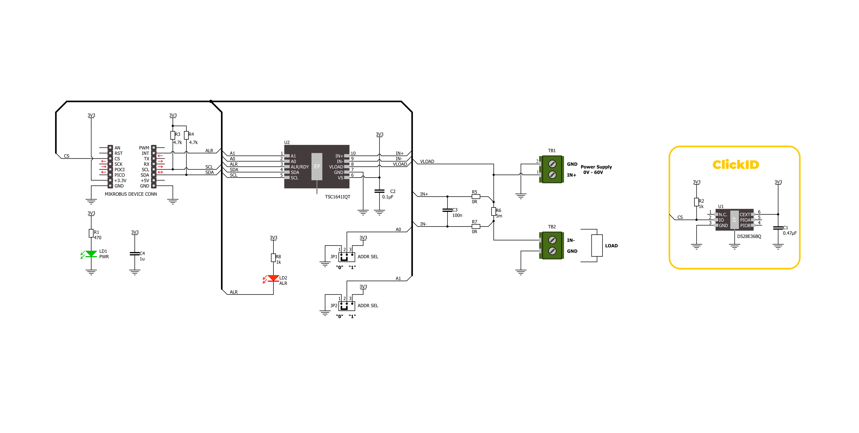
Current 12 Click is based on the TSC1641, a 60V 16-bit high-precision power monitor with an I2C interface from STMicroelectronics. The TSC1641 is a high-precision analog front-end (AFE) that monitors current, voltage, power, and temperature. It measures current through a shunt resistor and load voltage from 0V up to 60V in a synchronized manner. The current measurement can be high-side, low-side, and bidirectional. The device integrates a high-precision 16-bit resolution dual-channel sigma-delta ADC with a programmable
conversion time ranging from 128µs to 32.7ms. This board makes it ideal for applications such as industrial battery packs, power inverters, DC power supplies, data centers, telecom equipment, power tools, and more. Current 12 Click uses a standard 2-wire I2C communication protocol to enable the host MCU to control the TSC1641. The I2C interface supports clock frequencies of up to 1MHz, with the I2C address selectable via the ADDR SEL jumpers. The alert interrupt ALR pin allows the assertion of several alerts regarding voltage,
current, power, and temperature, with thresholds that can be set for each parameter in a specific register. This Click board™ can be operated only with a 3.3V logic voltage level. The board must perform appropriate logic voltage level conversion before using MCUs with different logic levels. Also, it comes equipped with a library containing functions and an example code that can be used as a reference for further development.

Features overview
Development board
Discovery kit with STM32F407VG MCU, powered by the STM32F407 microcontroller, simplifies audio application development. It offers a robust platform with features like the ST-LINK/V2-A debugger, STMEMS digital accelerometer, digital microphone, and integrated audio DAC with a class D speaker driver. It has LEDs, push buttons, and a USB OTG
Micro-AB connector for versatile connectivity. The STM32F407VGT6 MCU boasts a 32-bit Arm Cortex-M4 with FPU, 1MB Flash memory, and 192KB RAM, housed in an LQFP100 package. Equipped with USB OTG FS, MEMS accelerometer, omnidirectional digital microphone, and user-friendly buttons, it ensures seamless operation.
The board accommodates various add-ons via extension headers while offering flexible power supply options, including ST-LINK, USB VBUS, or external sources. Supported by comprehensive free software and a range of IDEs, it empowers developers with flexibility and ease of use, making it an ideal choice for audio-centric projects.

Microcontroller Overview
MCU Card / MCU

Architecture
ARM Cortex-M4
MCU Memory (KB)
10
Silicon Vendor
STMicroelectronics
Pin count
100
RAM (Bytes)
100
You complete me!
Accessories
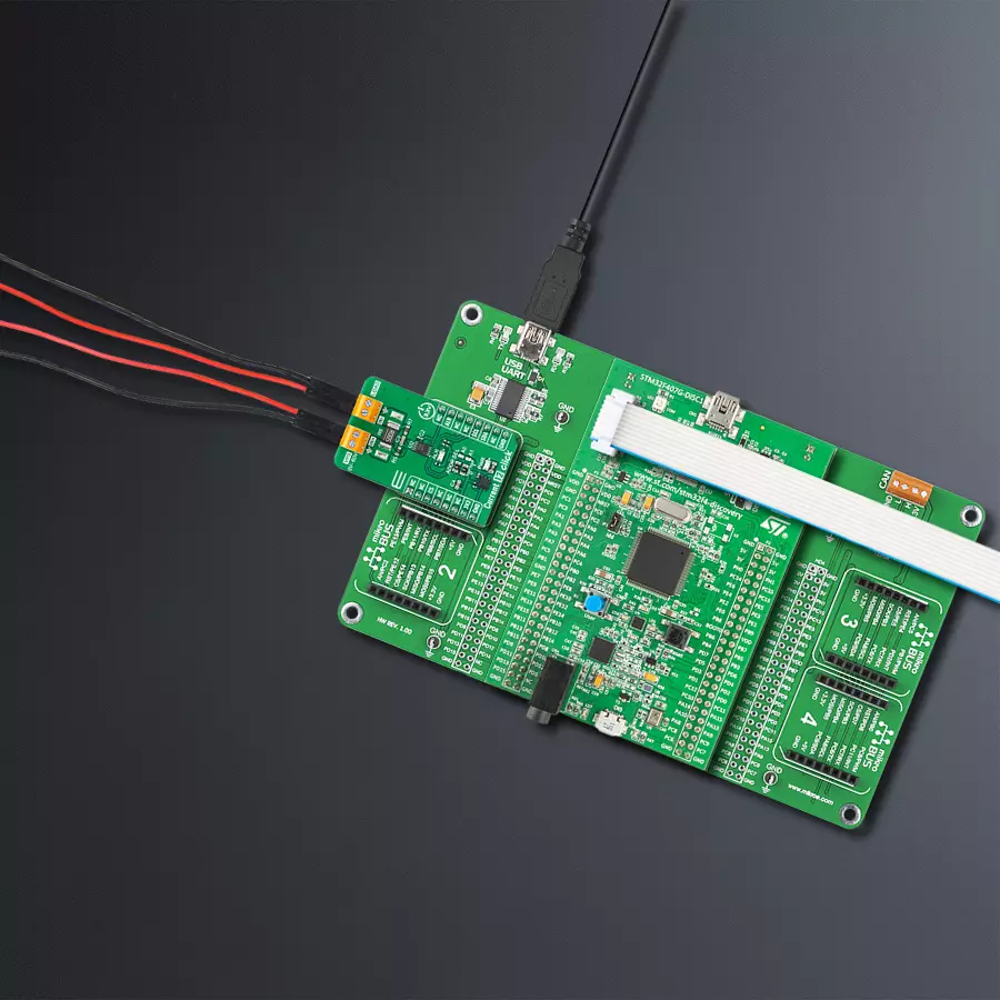
STM32F4 Discovery Shield is the perfect extension for your STM32F4 Discovery Board from STMicroelectronics. This versatile shield features four mikroBUS™ host sockets, a USB-UART module, and a CAN transceiver, expanding the capabilities of your Discovery board. Acting as a docking station, the STM32F4 Discovery Shield enables you to effortlessly transform your board into various applications, whether it's an RFID lock, SMS-triggered control switch, GPS tracking device, full-blown weather station, or any other idea you have in mind. With its seamless integration and enhanced functionality, this shield empowers you to explore endless possibilities and quickly bring your projects to life.

Used MCU Pins
mikroBUS™ mapper
Take a closer look
Click board™ Schematic
Step by step
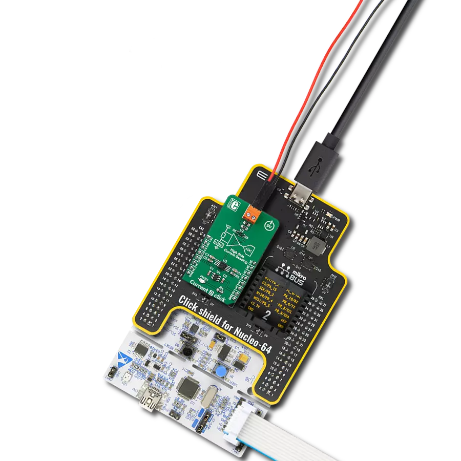
Project assembly

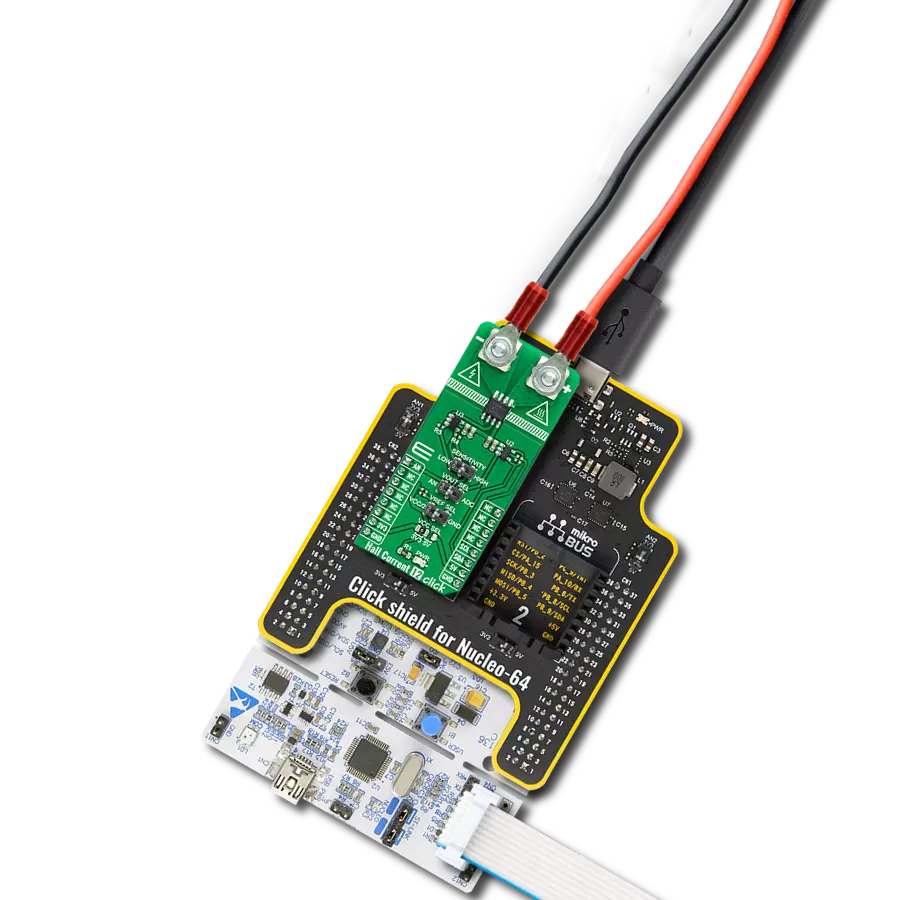
Start by selecting your development board and Click board™. Begin with the Discovery kit with STM32F407VG MCU as your development board.


Track your results in real time
Application Output
1. Application Output - In Debug mode, the 'Application Output' window enables real-time data monitoring, offering direct insight into execution results. Ensure proper data display by configuring the environment correctly using the provided tutorial.

2. UART Terminal - Use the UART Terminal to monitor data transmission via a USB to UART converter, allowing direct communication between the Click board™ and your development system. Configure the baud rate and other serial settings according to your project's requirements to ensure proper functionality. For step-by-step setup instructions, refer to the provided tutorial.

3. Plot Output - The Plot feature offers a powerful way to visualize real-time sensor data, enabling trend analysis, debugging, and comparison of multiple data points. To set it up correctly, follow the provided tutorial, which includes a step-by-step example of using the Plot feature to display Click board™ readings. To use the Plot feature in your code, use the function: plot(*insert_graph_name*, variable_name);. This is a general format, and it is up to the user to replace 'insert_graph_name' with the actual graph name and 'variable_name' with the parameter to be displayed.

Software Support
Library Description
This library contains API for Current 12 Click driver.
Key functions:
current12_get_load_voltage- This function reads the load voltage measurement values [V].current12_get_dc_power- This function reads the DC power measurement values [W].current12_get_current- This function reads the current measurement values [mA].
Open Source
Code example
The complete application code and a ready-to-use project are available through the NECTO Studio Package Manager for direct installation in the NECTO Studio. The application code can also be found on the MIKROE GitHub account.
/*!
* @file main.c
* @brief Current 12 Click example
*
* # Description
* This example demonstrates the use of the Current 12 Click board
* by reading and displaying the input current measurements.
*
* The demo application is composed of two sections :
*
* ## Application Init
* The initialization of the I2C module and log UART.
* After driver initialization, the app sets the default configuration.
*
* ## Application Task
* The demo application reads and displays the results
* of the input current, voltage, and power measurements.
* Results are being sent to the UART Terminal, where you can track their changes.
*
* @author Nenad Filipovic
*
*/
#include "board.h"
#include "log.h"
#include "current12.h"
static current12_t current12;
static log_t logger;
void application_init ( void )
{
log_cfg_t log_cfg; /**< Logger config object. */
current12_cfg_t current12_cfg; /**< Click config object. */
/**
* Logger initialization.
* Default baud rate: 115200
* Default log level: LOG_LEVEL_DEBUG
* @note If USB_UART_RX and USB_UART_TX
* are defined as HAL_PIN_NC, you will
* need to define them manually for log to work.
* See @b LOG_MAP_USB_UART macro definition for detailed explanation.
*/
LOG_MAP_USB_UART( log_cfg );
log_init( &logger, &log_cfg );
log_info( &logger, " Application Init " );
// Click initialization.
current12_cfg_setup( ¤t12_cfg );
CURRENT12_MAP_MIKROBUS( current12_cfg, MIKROBUS_1 );
if ( I2C_MASTER_ERROR == current12_init( ¤t12, ¤t12_cfg ) )
{
log_error( &logger, " Communication init." );
for ( ; ; );
}
if ( CURRENT12_ERROR == current12_default_cfg ( ¤t12 ) )
{
log_error( &logger, " Default configuration." );
for ( ; ; );
}
log_info( &logger, " Application Task " );
log_printf( &logger, "_____________________\r\n " );
Delay_ms ( 100 );
}
void application_task ( void )
{
float meas_data = 0;
if ( CURRENT12_OK == current12_get_shunt_voltage( ¤t12, &meas_data ) )
{
log_printf( &logger, " Shunt Voltage: %.2f [mV]\r\n ", meas_data );
Delay_ms ( 100 );
}
if ( CURRENT12_OK == current12_get_load_voltage( ¤t12, &meas_data ) )
{
log_printf( &logger, " Load Voltage: %.2f [V]\r\n ", meas_data );
Delay_ms ( 100 );
}
if ( CURRENT12_OK == current12_get_dc_power( ¤t12, &meas_data ) )
{
log_printf( &logger, " DC Power: %.2f [W]\r\n ", meas_data );
Delay_ms ( 100 );
}
if ( CURRENT12_OK == current12_get_current( ¤t12, &meas_data ) )
{
log_printf( &logger, " Current: %.2f [mA]\r\n", meas_data );
Delay_ms ( 100 );
}
log_printf( &logger, "_____________________\r\n " );
Delay_ms ( 1000 );
Delay_ms ( 1000 );
}
int main ( void )
{
/* Do not remove this line or clock might not be set correctly. */
#ifdef PREINIT_SUPPORTED
preinit();
#endif
application_init( );
for ( ; ; )
{
application_task( );
}
return 0;
}
// ------------------------------------------------------------------------ END
Additional Support
Resources
Category:Current sensor