Ensure seamless data transmission using ADuM341E and STM32F413ZH
SPI Isolator: The key to reliable data transmission
Published Feb 14, 2024
Click board™
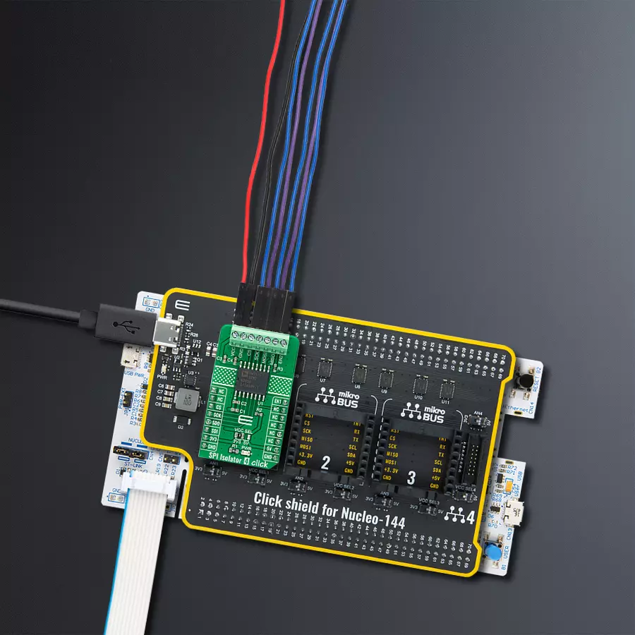
SPI Isolator 4 Click
Dev. board
Nucleo 144 with STM32F413ZH MCU
Compiler
NECTO Studio
MCU
STM32F413ZH
This isolator allows you to bridge the gap between systems with different ground references, ensuring that data is transmitted accurately and without disruptions
A
A
Hardware Overview
How does it work?
SPI Isolator 4 Click is based on the ADuM341E, a quad-channel digital isolator optimized for a serial peripheral interface from Analog Devices. This isolation component provides outstanding performance characteristics by combining high-speed and CMOS technology. It uses a high-frequency carrier to transmit data across the isolation barrier using iCoupler chip scale transformer coils separated by layers of polyimide isolation. Its data channels are independent and available in various configurations with a withstand voltage rating of 5kVrms. Using an ON/OFF keying (OOK) technique and the differential architecture, the ADuM341E has a very low propagation delay and high speed. It operates
with the external supply voltage ranging from 2.25V to 5.5V, providing compatibility with lower voltage systems and enabling voltage translation functionality across the isolation barrier. The ADuM341E architecture is designed for high common-mode transient (CMTI) immunity and high immunity to electrical noise and magnetic interference. Unlike other optocoupler alternatives, DC correctness is ensured without input logic transitions. Two different fail-safe options are available, by which the outputs go into a predetermined state when the input power supply is not applied or the inputs are disabled. SPI Isolator 4 Click communicates with an MCU using the SPI serial interface with a maximum data rate
of 100Mbps. This Click board™ also comes with an SDO line enable control pin, labeled as EN1, routed on the PWM pin of the mikroBUS™ socket. When EN1 is in a high logic state, the SDO line is enabled, and when EN1 is in a low logic state, the SDO line is disabled to the high-Z state. This Click board™ can operate with either 3.3V or 5V logic voltage levels selected via the VCC SEL jumper. This way, both 3.3V and 5V capable MCUs can use the communication lines properly. Also, this Click board™ comes equipped with a library containing easy-to-use functions and an example code that can be used as a reference for further development.


Features overview
Development board
Nucleo-144 with STM32F413ZH MCU board offers an accessible and adaptable avenue for users to explore new ideas and construct prototypes. It allows users to tailor their experience by selecting from a range of performance and power consumption features offered by the STM32 microcontroller. With compatible boards, the
internal or external SMPS dramatically decreases power usage in Run mode. Including the ST Zio connector, expanding ARDUINO Uno V3 connectivity, and ST morpho headers facilitate easy expansion of the Nucleo open development platform. The integrated ST-LINK debugger/programmer enhances convenience by
eliminating the need for a separate probe. Moreover, the board is accompanied by comprehensive free software libraries and examples within the STM32Cube MCU Package, further enhancing its utility and value.

Microcontroller Overview
MCU Card / MCU

Architecture
ARM Cortex-M4
MCU Memory (KB)
1536
Silicon Vendor
STMicroelectronics
Pin count
144
RAM (Bytes)
327680
You complete me!
Accessories
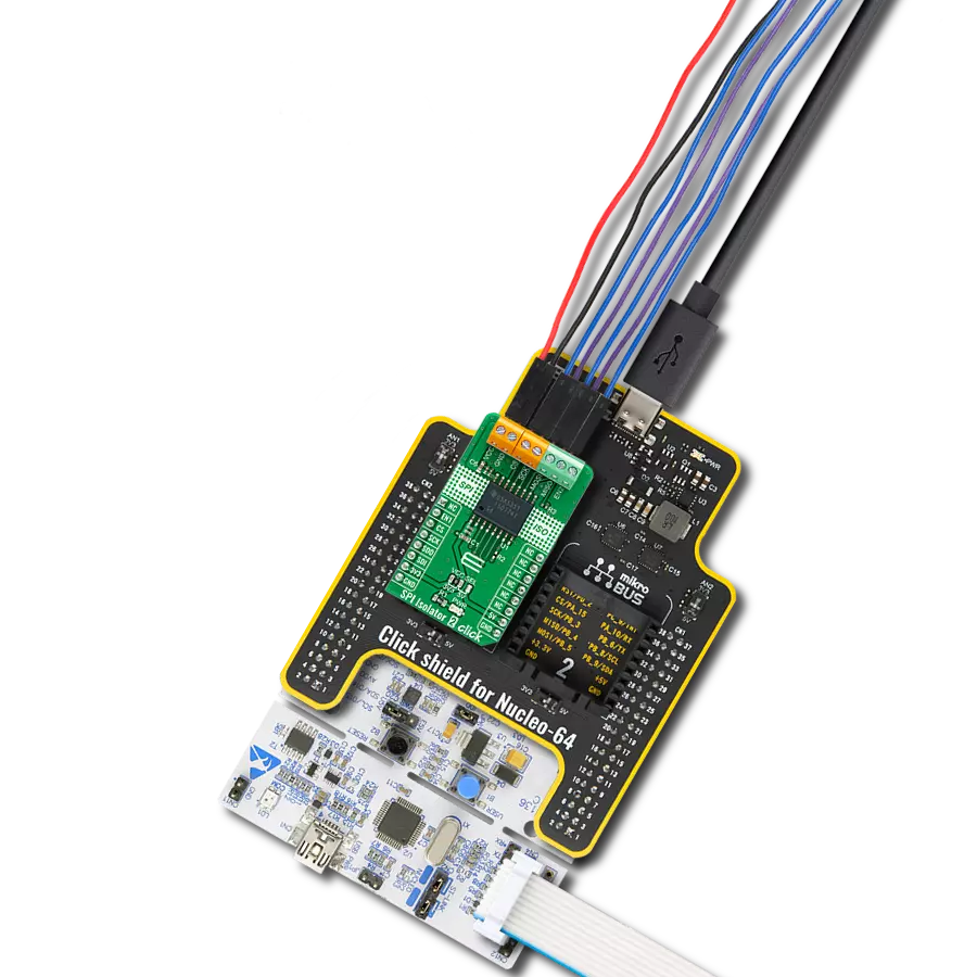
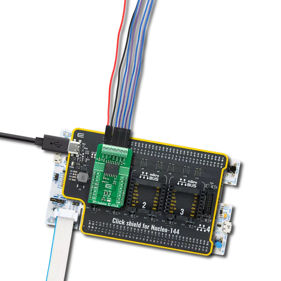
Click Shield for Nucleo-144 comes equipped with four mikroBUS™ sockets, with one in the form of a Shuttle connector, allowing all the Click board™ devices to be interfaced with the STM32 Nucleo-144 board with no effort. This way, MIKROE allows its users to add any functionality from our ever-growing range of Click boards™, such as WiFi, GSM, GPS, Bluetooth, ZigBee, environmental sensors, LEDs, speech recognition, motor control, movement sensors, and many more. Featuring an ARM Cortex-M microcontroller, 144 pins, and Arduino™ compatibility, the STM32 Nucleo-144 board offers limitless possibilities for prototyping and creating diverse applications. These boards are controlled and powered conveniently through a USB connection to program and efficiently debug the Nucleo-144 board out of the box, with an additional USB cable connected to the USB mini port on the board. Simplify your project development with the integrated ST-Link debugger and unleash creativity using the extensive I/O options and expansion capabilities. This Click Shield also has several switches that perform functions such as selecting the logic levels of analog signals on mikroBUS™ sockets and selecting logic voltage levels of the mikroBUS™ sockets themselves. Besides, the user is offered the possibility of using any Click board™ with the help of existing bidirectional level-shifting voltage translators, regardless of whether the Click board™ operates at a 3.3V or 5V logic voltage level. Once you connect the STM32 Nucleo-144 board with our Click Shield for Nucleo-144, you can access hundreds of Click boards™, working with 3.3V or 5V logic voltage levels.

Used MCU Pins
mikroBUS™ mapper
Take a closer look
Click board™ Schematic

Step by step
Project assembly
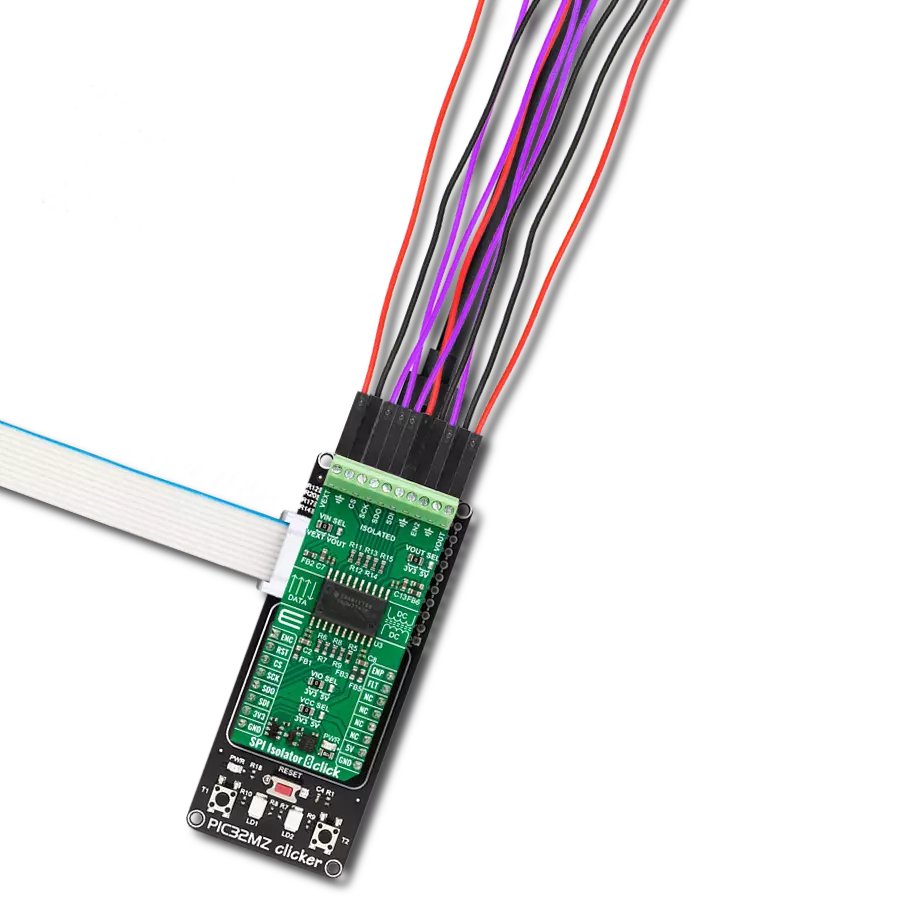
Start by selecting your development board and Click board™. Begin with the Nucleo 144 with STM32F413ZH MCU as your development board.


Software Support
Library Description
This library contains API for SPI Isolator 4 Click driver.
Key functions:
spiisolator4_generic_write- SPI Isolator 4 data writing functionspiisolator4_generic_read- SPI Isolator 4 data reading function
Open Source
Code example
The complete application code and a ready-to-use project are available through the NECTO Studio Package Manager for direct installation in the NECTO Studio. The application code can also be found on the MIKROE GitHub account.
/*!
 * @file main.c
 * @brief SPIIsolator4 Click example
 *
 * # Description
 * This library contains API for the SPI Isolator 4 Click driver.
 * This demo application shows an example of an SPI Isolator 4 Click wired
 * to the nvSRAM 4 Click for reading Device ID.
 *
 * The demo application is composed of two sections :
 *
 * ## Application Init
 * Initialization of SPI module and log UART.
 * After driver initialization, the app sets the default configuration.
 *
 * ## Application Task
 * This is an example that shows the use of an SPI Isolator 4 Click board™.
 * Logs Device ID of the nvSRAM 4 Click wired to the SPI Isolator 4 board™.
 * Results are being sent to the Usart Terminal where you can track their changes.
 *
 * ## Additional Function
 * - static void get_device_id ( void )
 *
 * @author Mikroe Team
 *
 */

#include "board.h"
#include "log.h"
#include "spiisolator4.h"

static spiisolator4_t spiisolator4;
static log_t logger;
static uint32_t device_id;

static void get_device_id ( void ) {
    uint8_t rx_data[ 4 ];

    spiisolator4_generic_read( &spiisolator4, 0x9F, &rx_data[ 0 ], 4 );

    device_id = rx_data[ 0 ];
    device_id <<= 8;
    device_id |= rx_data[ 1 ];
    device_id <<= 8;
    device_id |= rx_data[ 2 ];
    device_id <<= 8;
    device_id |= rx_data[ 3 ];
}

void application_init ( void )
{
    log_cfg_t log_cfg;                    /**< Logger config object. */
    spiisolator4_cfg_t spiisolator4_cfg;  /**< Click config object. */

    /**
     * Logger initialization.
     * Default baud rate: 115200
     * Default log level: LOG_LEVEL_DEBUG
     * @note If USB_UART_RX and USB_UART_TX
     * are defined as HAL_PIN_NC, you will
     * need to define them manually for log to work.
     * See @b LOG_MAP_USB_UART macro definition for detailed explanation.
     */
    LOG_MAP_USB_UART( log_cfg );
    log_init( &logger, &log_cfg );
    log_info( &logger, " Application Init " );

    // Click initialization.

    spiisolator4_cfg_setup( &spiisolator4_cfg );
    SPIISOLATOR4_MAP_MIKROBUS( spiisolator4_cfg, MIKROBUS_1 );
    err_t init_flag  = spiisolator4_init( &spiisolator4, &spiisolator4_cfg );
    if ( SPI_MASTER_ERROR == init_flag )
    {
        log_error( &logger, " Application Init Error. " );
        log_info( &logger, " Please, run program again... " );

        for ( ; ; );
    }

    spiisolator4_default_cfg ( &spiisolator4 );
    log_info( &logger, " Application Task " );
    log_printf( &logger, "--------------------------\r\n" );
    Delay_ms ( 100 );
}

void application_task ( void )
{
    get_device_id( );
    log_printf( &logger, "  Device ID : 0x%.8LX\r\n", device_id );
    log_printf( &logger, "--------------------------\r\n" );
    Delay_ms ( 1000 );
}

int main ( void )
{
    /* Do not remove this line or clock might not be set correctly. */
    #ifdef PREINIT_SUPPORTED
    preinit();
    #endif

    application_init( );

    for ( ; ; )
    {
        application_task( );
    }

    return 0;
}

// ------------------------------------------------------------------------ END
Additional Support
Resources
Category:SPI