Ensure the air you breathe is of the highest quality using SGP30 and STM32F446RE
See the unseen, breathe the pure

Published Oct 08, 2024
Click board™
Air quality 4 Click
Dev. board
Nucleo 64 with STM32F446RE MCU
Compiler
NECTO Studio
MCU
STM32F446RE
From homes to workplaces, our air quality monitor solution seamlessly integrates into any environment, providing real-time insights for a safer, cleaner lifestyle
A
A
Hardware Overview
How does it work?
Air Quality 4 Click is based on the SGP30 from Sensirion, a multi-pixel gas sensor for indoor applications. This sensor is a system of several metal-oxide sensing elements on a chip (pixels), used to measure and process readings of various gasses in the air and output them in the form of two complementary air quality readings - Total Volatile Organic Compounds (TVOC) [ppb] and CO2 equivalent signal [ppm]. The traditional metal-oxide (MOX) sensors suffer from sensitivity and responsiveness degradation after siloxane exposure. Siloxanes are compounds commonly found in the air, negatively affecting the MOX sensors. To overcome this problem, the SGP30 sensors use the advanced MOXSens® Technology, which provides unmatched robustness against siloxane contamination. This results in unprecedented long-term stability and accuracy. The SGP30 uses a dynamic baseline compensation algorithm and calibration parameters to record TVOC and CO2eq properties accurately. These baseline values of the compensation algorithm
can be stored externally and read back into the device with the appropriate I2C commands and can be used in the event of power down or restart. For the first 15 seconds after the I2C initialization command, the sensor is in an initialization phase of collecting sensor measurements and baseline compensation data. When the measurement command is attempted, it will return fixed values of 400 ppm CO2eq and 0 ppb TVOC. The device also allows air humidity corrections over the results for both the compensated and raw values. However, an absolute humidity sensor should be used for obtaining the humidity reading. Readings from SHT click or similar humidity-measuring devices can be used for this purpose. The appropriate I2C command will store the value in the on-chip memory and perform the corrections accordingly. Additional components on Air Quality 4 clicks are used to provide necessary voltage levels for the SGP30 sensor IC. This sensor has a common voltage level of 1.8V, so to provide proper communication with 3.3V and 5V capable MCUs, a
small LDO voltage regulator has to be used, along with the level shifter, which provides the required logic voltage levels. The SPX3819M5, a small 500mA LDO voltage regulator, provides a power supply of 1.8V for the SGP30. The PCA9306 dual bidirectional I2C bus and SMBus voltage level shifter are used for the level shifting. This level shifter IC allows shifting (converting) the I2C signal levels to the voltage level selected by the VCC SEL onboard SMD jumper. This allows 3.3V and 5V capable MCUs to be interfaced with the Air quality 4 Click. More detailed information about all the available I2C commands can be found in the SGP30 datasheet. However, all the functions and commands necessary to perform air quality readings and functions used to calculate H2 and Ethanol concentration levels are contained within the Air Quality 4 click libraries provided with this click board™. Their usage is demonstrated in the included example application, which can be used as a reference for a custom application design.


Features overview
Development board
Nucleo-64 with STM32F446RE MCU offers a cost-effective and adaptable platform for developers to explore new ideas and prototype their designs. This board harnesses the versatility of the STM32 microcontroller, enabling users to select the optimal balance of performance and power consumption for their projects. It accommodates the STM32 microcontroller in the LQFP64 package and includes essential components such as a user LED, which doubles as an ARDUINO® signal, alongside user and reset push-buttons, and a 32.768kHz crystal oscillator for precise timing operations. Designed with expansion and flexibility in mind, the Nucleo-64 board features an ARDUINO® Uno V3 expansion connector and ST morpho extension pin
headers, granting complete access to the STM32's I/Os for comprehensive project integration. Power supply options are adaptable, supporting ST-LINK USB VBUS or external power sources, ensuring adaptability in various development environments. The board also has an on-board ST-LINK debugger/programmer with USB re-enumeration capability, simplifying the programming and debugging process. Moreover, the board is designed to simplify advanced development with its external SMPS for efficient Vcore logic supply, support for USB Device full speed or USB SNK/UFP full speed, and built-in cryptographic features, enhancing both the power efficiency and security of projects. Additional connectivity is
provided through dedicated connectors for external SMPS experimentation, a USB connector for the ST-LINK, and a MIPI® debug connector, expanding the possibilities for hardware interfacing and experimentation. Developers will find extensive support through comprehensive free software libraries and examples, courtesy of the STM32Cube MCU Package. This, combined with compatibility with a wide array of Integrated Development Environments (IDEs), including IAR Embedded Workbench®, MDK-ARM, and STM32CubeIDE, ensures a smooth and efficient development experience, allowing users to fully leverage the capabilities of the Nucleo-64 board in their projects.

Microcontroller Overview
MCU Card / MCU

Architecture
ARM Cortex-M4
MCU Memory (KB)
512
Silicon Vendor
STMicroelectronics
Pin count
64
RAM (Bytes)
131072
You complete me!
Accessories
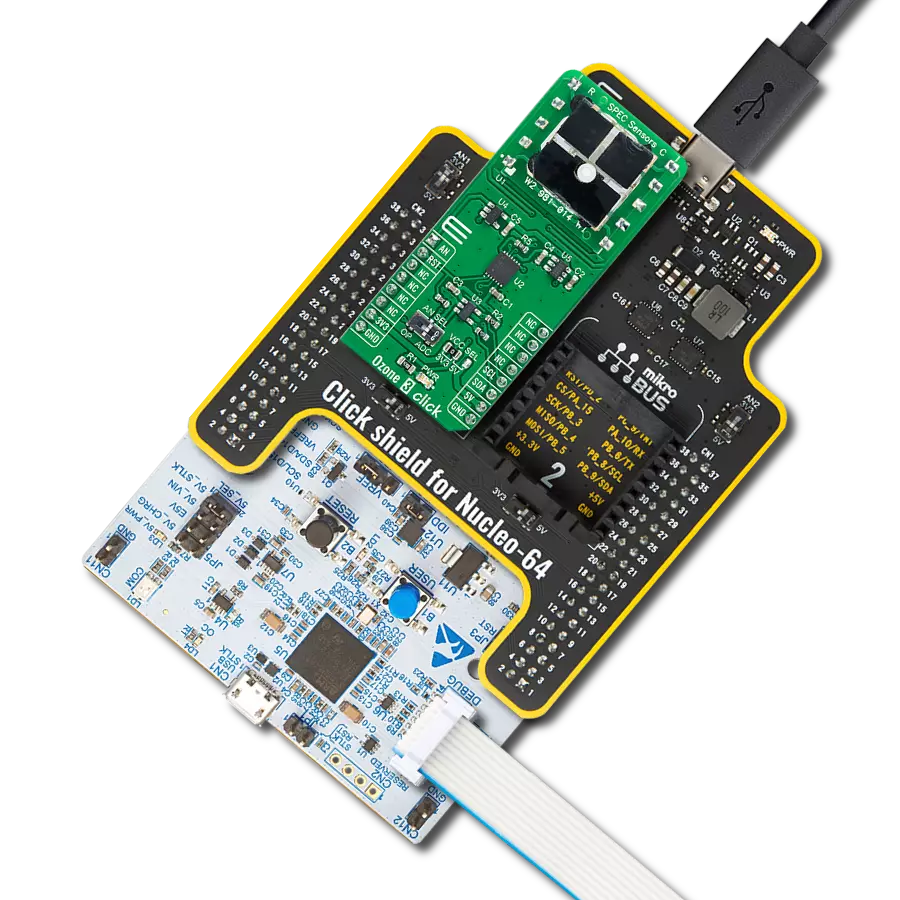
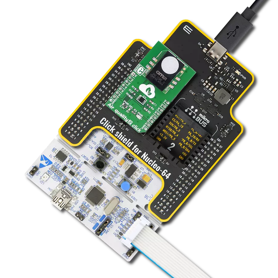
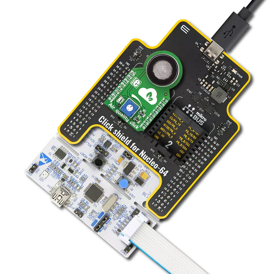
Click Shield for Nucleo-64 comes equipped with two proprietary mikroBUS™ sockets, allowing all the Click board™ devices to be interfaced with the STM32 Nucleo-64 board with no effort. This way, Mikroe allows its users to add any functionality from our ever-growing range of Click boards™, such as WiFi, GSM, GPS, Bluetooth, ZigBee, environmental sensors, LEDs, speech recognition, motor control, movement sensors, and many more. More than 1537 Click boards™, which can be stacked and integrated, are at your disposal. The STM32 Nucleo-64 boards are based on the microcontrollers in 64-pin packages, a 32-bit MCU with an ARM Cortex M4 processor operating at 84MHz, 512Kb Flash, and 96KB SRAM, divided into two regions where the top section represents the ST-Link/V2 debugger and programmer while the bottom section of the board is an actual development board. These boards are controlled and powered conveniently through a USB connection to program and efficiently debug the Nucleo-64 board out of the box, with an additional USB cable connected to the USB mini port on the board. Most of the STM32 microcontroller pins are brought to the IO pins on the left and right edge of the board, which are then connected to two existing mikroBUS™ sockets. This Click Shield also has several switches that perform functions such as selecting the logic levels of analog signals on mikroBUS™ sockets and selecting logic voltage levels of the mikroBUS™ sockets themselves. Besides, the user is offered the possibility of using any Click board™ with the help of existing bidirectional level-shifting voltage translators, regardless of whether the Click board™ operates at a 3.3V or 5V logic voltage level. Once you connect the STM32 Nucleo-64 board with our Click Shield for Nucleo-64, you can access hundreds of Click boards™, working with 3.3V or 5V logic voltage levels.

Used MCU Pins
mikroBUS™ mapper
Take a closer look
Click board™ Schematic

Step by step
Project assembly
Start by selecting your development board and Click board™. Begin with the Nucleo 64 with STM32F446RE MCU as your development board.


Track your results in real time
Application Output
1. Application Output - In Debug mode, the 'Application Output' window enables real-time data monitoring, offering direct insight into execution results. Ensure proper data display by configuring the environment correctly using the provided tutorial.

2. UART Terminal - Use the UART Terminal to monitor data transmission via a USB to UART converter, allowing direct communication between the Click board™ and your development system. Configure the baud rate and other serial settings according to your project's requirements to ensure proper functionality. For step-by-step setup instructions, refer to the provided tutorial.

3. Plot Output - The Plot feature offers a powerful way to visualize real-time sensor data, enabling trend analysis, debugging, and comparison of multiple data points. To set it up correctly, follow the provided tutorial, which includes a step-by-step example of using the Plot feature to display Click board™ readings. To use the Plot feature in your code, use the function: plot(*insert_graph_name*, variable_name);. This is a general format, and it is up to the user to replace 'insert_graph_name' with the actual graph name and 'variable_name' with the parameter to be displayed.

Software Support
Library Description
This library contains API for Air Quality 4 Click driver.
Key functions:
air_quality4_soft_reset- This function calls general reset witch resets all states on the chipair_quality4_get_co2_and_tvoc- This function writes 2 bytes CO2 data and 2 bytes TVOC data without CRC dataair_quality4_get_h2_and_ehtoh- This function writes 2 bytes H2 data and 2 bytes EthOH data without CRC data
Open Source
Code example
The complete application code and a ready-to-use project are available through the NECTO Studio Package Manager for direct installation in the NECTO Studio. The application code can also be found on the MIKROE GitHub account.
/*!
 * \file
 * \brief AirQuality4 Click example
 *
 * # Description
 * This application measures the amount of substances in air and air quality and logs the results.
 *
 * The demo application is composed of two sections :
 *
 * ## Application Init
 * nitializes Click driver and gets ID data.
 *
 * ## Application Task
 * Performs measurements of air concentracion for H2, EthOH, CO2 and TVOC data.
 * Results of measurement shows on USBUART.
 *
 * \author MikroE Team
 *
 */
// ------------------------------------------------------------------- INCLUDES

#include "board.h"
#include "log.h"
#include "airquality4.h"

// ------------------------------------------------------------------ VARIABLES

static airquality4_t airquality4;
static log_t logger;
static uint8_t buffer_data[ 6 ];
static uint16_t data_buffer[ 2 ];

// ------------------------------------------------------ APPLICATION FUNCTIONS

void application_init ( void )
{
    log_cfg_t log_cfg;
    airquality4_cfg_t cfg;

    /**
     * Logger initialization.
     * Default baud rate: 115200
     * Default log level: LOG_LEVEL_DEBUG
     * @note If USB_UART_RX and USB_UART_TX
     * are defined as HAL_PIN_NC, you will
     * need to define them manually for log to work.
     * See @b LOG_MAP_USB_UART macro definition for detailed explanation.
     */
    LOG_MAP_USB_UART( log_cfg );
    log_init( &logger, &log_cfg );
    log_info( &logger, "---- Application Init ----" );

    //  Click initialization.

    airquality4_cfg_setup( &cfg );
    AIRQUALITY4_MAP_MIKROBUS( cfg, MIKROBUS_1 );
    airquality4_init( &airquality4, &cfg );
    airquality4_default_cfg( &airquality4 );
}

void application_task ( void )
{
    air_quality4_get_h2_and_ethon( &airquality4, data_buffer);

    log_printf( &logger, "H2 value is: %u\n", data_buffer[ 0 ] );
    log_printf( &logger, "EthOH value is:  %u\n", data_buffer[ 1 ] );

    air_quality4_set_baseline( &airquality4 );
    air_quality4_get_co2_and_tvoc( &airquality4, &data_buffer[ 0 ] );

    log_printf( &logger, "CO2 value is: %u\n", data_buffer[ 0 ] );
    log_printf( &logger, "TVOC value is: %u\n\n", data_buffer[ 1 ] );

    Delay_ms ( 1000 );
}

int main ( void )
{
    /* Do not remove this line or clock might not be set correctly. */
    #ifdef PREINIT_SUPPORTED
    preinit();
    #endif

    application_init( );

    for ( ; ; )
    {
        application_task( );
    }

    return 0;
}


// ------------------------------------------------------------------------ END
Additional Support
Resources
Category:Gas