Easily select and process analog signals from multiple sources with MAX4634 and STM32L073RZ
Switch to perfection

Published Feb 26, 2024
Click board™
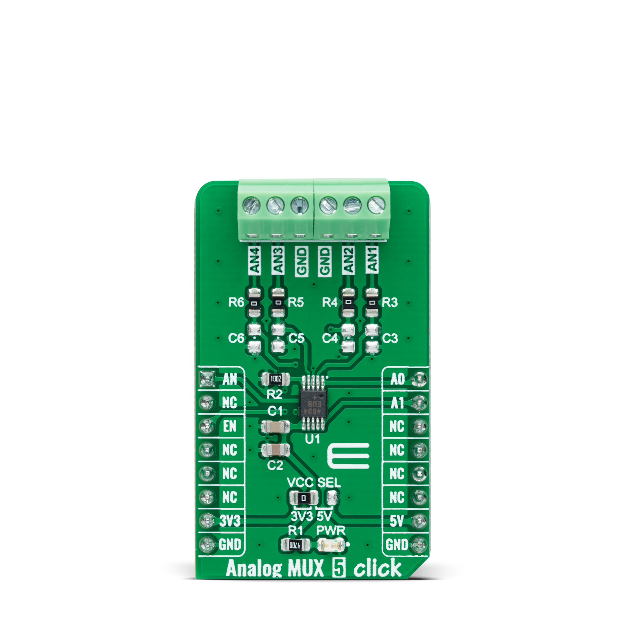
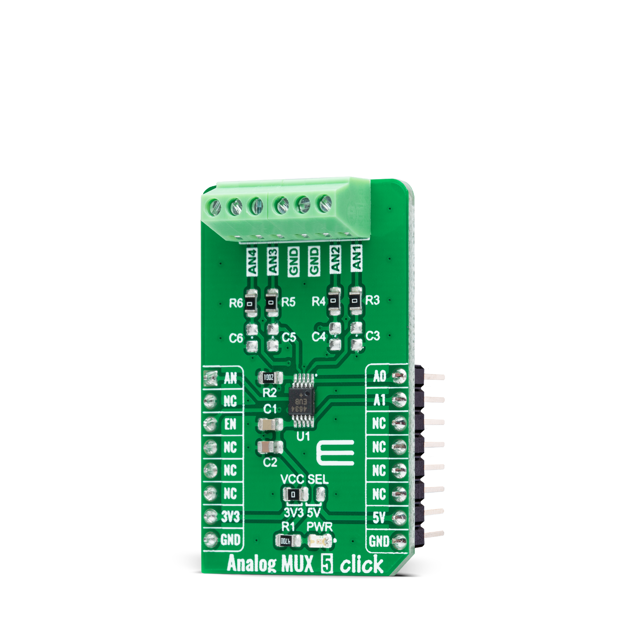
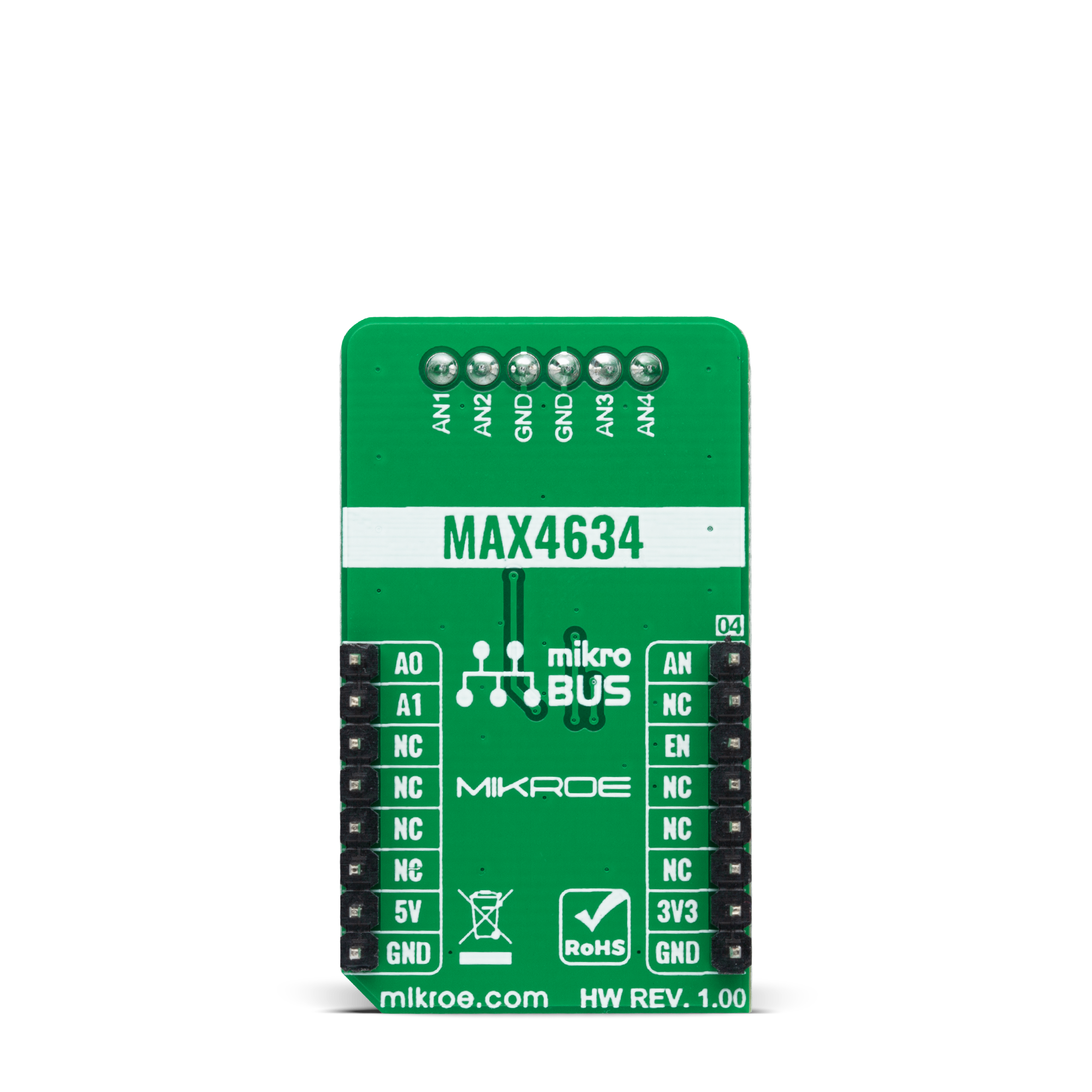
Analog MUX 5 Click
Dev. board
Nucleo-64 with STM32L073RZ MCU
Compiler
NECTO Studio
MCU
STM32L073RZ
Experience the power of precise and low-voltage analog data switching for uncompromised audio, video, data-acquisition applications, and many more
A
A
Hardware Overview
How does it work?
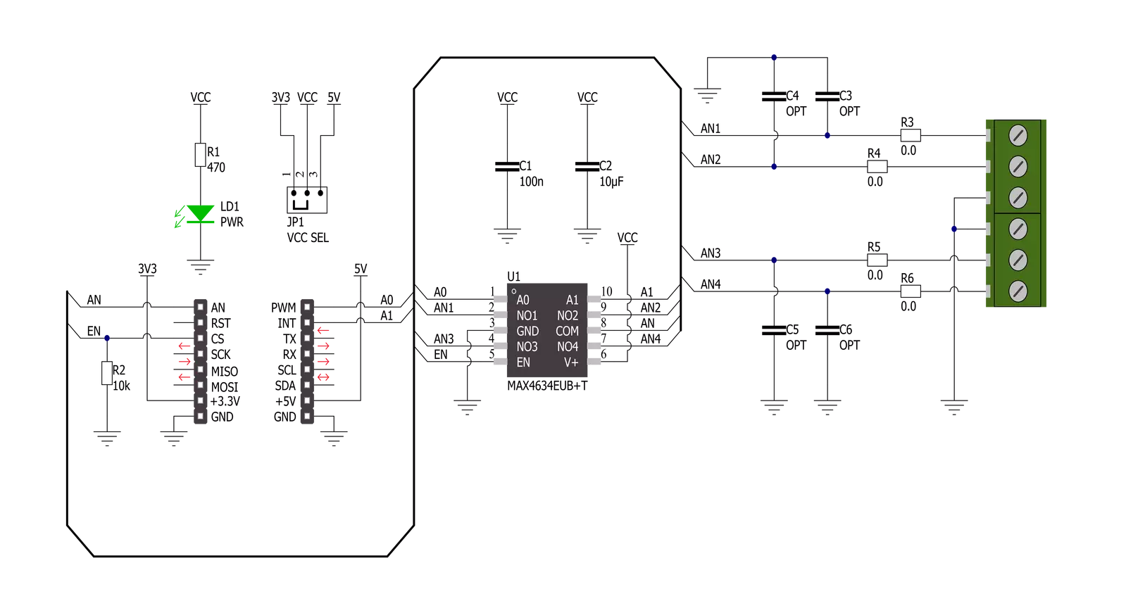
Analog MUX 5 Click is based on the MAX4634, a low-on-resistance, low-voltage analog multiplexer from Analog Devices. CMOS switch construction of the MAX4634 allows the processing of analog signals within its supply voltage range. It features 4Ω maximum ON-resistance (RON) and offers RON matching between switches to 0.3Ω maximum and RON flatness of 1Ω maximum over the specified signal range. Also, all digital inputs have +0.8V and +2.4V logic thresholds, ensuring TTL/CMOS-logic compatibility with +5V operation. This Click board™ communicates with MCU using several GPIO pins.
It can be enabled or disabled through the EN pin routed to the CS pin of the mikroBUS™ socket, hence, offering a switch operation to turn ON/OFF power delivery to the MAX4634. It also provides two address signals, labeled as A0 and A1 and routed to the PWM and INT pins of the mikroBUS™ socket, that determine the activation of the desired analog input channel based on their setup while monitoring of that input analog signal is done using AN pin of the mikroBUS™ socket. Each analog input has a jumper for its hardware activation or deactivation from R3 to R6 and capacitors for additional filtering of the input
channels from C3 to C6. Proper power-supply sequencing is recommended for all CMOS devices. Before applying analog signals or logic inputs, always apply the power supply first, especially if the analog or logic signals are not current-limited. This Click board™ can operate with either 3.3V or 5V logic voltage levels selected via the VCC SEL jumper. This way, both 3.3V and 5V capable MCUs can use the communication lines properly. However, the Click board™ comes equipped with a library containing easy-to-use functions and an example code that can be used, as a reference, for further development.
Features overview
Development board
Nucleo-64 with STM32L073RZ MCU offers a cost-effective and adaptable platform for developers to explore new ideas and prototype their designs. This board harnesses the versatility of the STM32 microcontroller, enabling users to select the optimal balance of performance and power consumption for their projects. It accommodates the STM32 microcontroller in the LQFP64 package and includes essential components such as a user LED, which doubles as an ARDUINO® signal, alongside user and reset push-buttons, and a 32.768kHz crystal oscillator for precise timing operations. Designed with expansion and flexibility in mind, the Nucleo-64 board features an ARDUINO® Uno V3 expansion connector and ST morpho extension pin
headers, granting complete access to the STM32's I/Os for comprehensive project integration. Power supply options are adaptable, supporting ST-LINK USB VBUS or external power sources, ensuring adaptability in various development environments. The board also has an on-board ST-LINK debugger/programmer with USB re-enumeration capability, simplifying the programming and debugging process. Moreover, the board is designed to simplify advanced development with its external SMPS for efficient Vcore logic supply, support for USB Device full speed or USB SNK/UFP full speed, and built-in cryptographic features, enhancing both the power efficiency and security of projects. Additional connectivity is
provided through dedicated connectors for external SMPS experimentation, a USB connector for the ST-LINK, and a MIPI® debug connector, expanding the possibilities for hardware interfacing and experimentation. Developers will find extensive support through comprehensive free software libraries and examples, courtesy of the STM32Cube MCU Package. This, combined with compatibility with a wide array of Integrated Development Environments (IDEs), including IAR Embedded Workbench®, MDK-ARM, and STM32CubeIDE, ensures a smooth and efficient development experience, allowing users to fully leverage the capabilities of the Nucleo-64 board in their projects.

Microcontroller Overview
MCU Card / MCU

Architecture
ARM Cortex-M0
MCU Memory (KB)
192
Silicon Vendor
STMicroelectronics
Pin count
64
RAM (Bytes)
20480
You complete me!
Accessories
Click Shield for Nucleo-64 comes equipped with two proprietary mikroBUS™ sockets, allowing all the Click board™ devices to be interfaced with the STM32 Nucleo-64 board with no effort. This way, Mikroe allows its users to add any functionality from our ever-growing range of Click boards™, such as WiFi, GSM, GPS, Bluetooth, ZigBee, environmental sensors, LEDs, speech recognition, motor control, movement sensors, and many more. More than 1537 Click boards™, which can be stacked and integrated, are at your disposal. The STM32 Nucleo-64 boards are based on the microcontrollers in 64-pin packages, a 32-bit MCU with an ARM Cortex M4 processor operating at 84MHz, 512Kb Flash, and 96KB SRAM, divided into two regions where the top section represents the ST-Link/V2 debugger and programmer while the bottom section of the board is an actual development board. These boards are controlled and powered conveniently through a USB connection to program and efficiently debug the Nucleo-64 board out of the box, with an additional USB cable connected to the USB mini port on the board. Most of the STM32 microcontroller pins are brought to the IO pins on the left and right edge of the board, which are then connected to two existing mikroBUS™ sockets. This Click Shield also has several switches that perform functions such as selecting the logic levels of analog signals on mikroBUS™ sockets and selecting logic voltage levels of the mikroBUS™ sockets themselves. Besides, the user is offered the possibility of using any Click board™ with the help of existing bidirectional level-shifting voltage translators, regardless of whether the Click board™ operates at a 3.3V or 5V logic voltage level. Once you connect the STM32 Nucleo-64 board with our Click Shield for Nucleo-64, you can access hundreds of Click boards™, working with 3.3V or 5V logic voltage levels.

Used MCU Pins
mikroBUS™ mapper
Take a closer look
Click board™ Schematic
Step by step
Project assembly
Start by selecting your development board and Click board™. Begin with the Nucleo-64 with STM32L073RZ MCU as your development board.


Software Support
Library Description
This library contains API for Analog MUX 5 Click driver.
Key functions:
analogmux5_cfg_setup- Config Object Initialization function.analogmux5_init- Initialization function.analogmux5_default_cfg- Click Default Configuration function.
Open Source
Code example
The complete application code and a ready-to-use project are available through the NECTO Studio Package Manager for direct installation in the NECTO Studio. The application code can also be found on the MIKROE GitHub account.
/*!
 * @file main.c
 * @brief Analog MUX 5 Click Example.
 *
 * # Description
 * This example showcases how to initialize, configure and use the Analog MUX 5 Click module.
 *
 * The demo application is composed of two sections :
 *
 * ## Application Init
 * Initializes the driver and enables the analog inputs.
 *
 * ## Application Task
 * This is an example that shows the use of a Analog MUX 5 Click board.
 * In this example, we switch from channel AN1 to channel AN4,
 * read and display the voltage on the active channel.
 * Results are being sent to the Usart Terminal where you can track their changes.
 *
 *
 * @author Nikola Peric
 *
 */

#include "board.h"
#include "log.h"
#include "analogmux5.h"

static analogmux5_t analogmux5;   /**< Analog MUX 5 Click driver object. */
static log_t logger;              /**< Logger object. */

void application_init ( void )
{
    log_cfg_t log_cfg;                /**< Logger config object. */
    analogmux5_cfg_t analogmux5_cfg;  /**< Click config object. */

    /**
     * Logger initialization.
     * Default baud rate: 115200
     * Default log level: LOG_LEVEL_DEBUG
     * @note If USB_UART_RX and USB_UART_TX
     * are defined as HAL_PIN_NC, you will
     * need to define them manually for log to work.
     * See @b LOG_MAP_USB_UART macro definition for detailed explanation.
     */
    LOG_MAP_USB_UART( log_cfg );
    log_init( &logger, &log_cfg );
    log_info( &logger, " Application Init " );

    // Click initialization.
    analogmux5_cfg_setup( &analogmux5_cfg );
    ANALOGMUX5_MAP_MIKROBUS( analogmux5_cfg, MIKROBUS_1 );
    if ( ADC_ERROR == analogmux5_init( &analogmux5, &analogmux5_cfg ) )
    {
        log_error( &logger, " Communication init." );
        for ( ; ; );
    }

    if ( ANALOGMUX5_ERROR == analogmux5_default_cfg ( &analogmux5 ) )
    {
        log_error( &logger, " Default configuration." );
        for ( ; ; );
    }

    log_info( &logger, " Application Task " );
}

void application_task ( void )
{
    float analogmux5_an_voltage = 0;

    analogmux5_select_ch( &analogmux5, ANALOGMUX5_SEL_CH_1 );
    Delay_ms ( 100 );

    if ( ADC_ERROR != analogmux5_read_an_pin_voltage ( &analogmux5, &analogmux5_an_voltage ) )
    {
        log_printf( &logger, " Channel [ 1 ] ---> AN Voltage : %.3f[V]\r\n\n", analogmux5_an_voltage );
    }

    analogmux5_select_ch( &analogmux5, ANALOGMUX5_SEL_CH_2 );
    Delay_ms ( 100 );

    if ( ADC_ERROR != analogmux5_read_an_pin_voltage ( &analogmux5, &analogmux5_an_voltage ) )
    {
        log_printf( &logger, " Channel [ 2 ] ---> AN Voltage : %.3f[V]\r\n\n", analogmux5_an_voltage );
    }

    analogmux5_select_ch( &analogmux5, ANALOGMUX5_SEL_CH_3 );
    Delay_ms ( 100 );

    if ( ADC_ERROR != analogmux5_read_an_pin_voltage ( &analogmux5, &analogmux5_an_voltage ) )
    {
        log_printf( &logger, " Channel [ 3 ] ---> AN Voltage : %.3f[V]\r\n\n", analogmux5_an_voltage );
    }

    analogmux5_select_ch( &analogmux5, ANALOGMUX5_SEL_CH_4 );
    Delay_ms ( 100 );

    if ( ADC_ERROR != analogmux5_read_an_pin_voltage ( &analogmux5, &analogmux5_an_voltage ) )
    {
        log_printf( &logger, " Channel [ 4 ] ---> AN Voltage : %.3f[V]\r\n\n", analogmux5_an_voltage );
    }
    Delay_ms ( 1000 );
}

int main ( void )
{
    /* Do not remove this line or clock might not be set correctly. */
    #ifdef PREINIT_SUPPORTED
    preinit();
    #endif

    application_init( );

    for ( ; ; )
    {
        application_task( );
    }

    return 0;
}

// ------------------------------------------------------------------------ END
Additional Support
Resources
Category:Port expander


