Unlock the potential of H-bridge motor control with MPC17510 and STM32F091RC
Ignite your motors with unmatched control!

Published Feb 26, 2024
Click board™
H-Bridge 2 Click
Dev. board
Nucleo-64 with STM32F091RC MCU
Compiler
NECTO Studio
MCU
STM32F091RC
Achieve seamless control over the direction and speed of your brushed motors, enabling precise and efficient motion in a wide range of applications
A
A
Hardware Overview
How does it work?
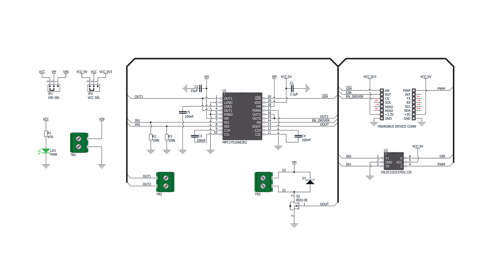
H-Bridge 2 Click is based on the MPC17510, an H-Bridge DC motor driver with up to 15V and 1.2A from NXP Semiconductors. This IC is an efficient integrated H-bridge driver with very low RDS ON output stage MOSFETs. H-bridge, in general, allows the current to flow in one or another direction. To achieve this, a special network of four output MOSFETs is used so that only two conduct the current through the source. Switching the MOSFET pairs' biasing allows current to flow in both directions. A particular problem can be the simultaneous switching of all MOSFETs, which results in short-circuit through a pair of MOSFETs. This leads to the destruction of the IC. The MPC17510 employs cross-conduction suppression timings and logic to prevent this, ensuring that only one pair of MOSFETs is conducted at a time. Suppose the input voltage of either the logic section or the power section drops under the detection threshold. In that case, the H-Bridge 2 click outputs will become tri-stated, meaning that the outputs will be put into a high impedance mode (disconnected). The onboard jumper labeled VIN SEL allows selection between the mikroBUS™ power rail (selected by another jumper, labeled as VCC SEL) and the external voltage input (up to 15V) from the VIN screw terminal. It should be noted that the mikroBUS™ only allows enough power for light loads (smaller
motors); thus, the external voltage input should be selected when working with heavier loads. H-Bridge 2 Click is controlled via several pins. The EN pin of the MPC17510 is routed to the CS pin of the mikroBUS™, which is labeled as END on the Click board™. When set to a HIGH logic level, this pin enables the IC itself. Pulling this pin to a LOW logic state will make both low-side MOSFETs biased and conductive, performing the dynamic motor braking. The pin is pulled up internally, so the IC will be enabled, even if the END pin is left afloat. The #GIN pin is used to drive the gate of the external MOSFET. This pin is routed to the AN pin of the mikroBUS™, labeled as the GIN. The Click board™ can drive an external MOSFET, which can be used as an auxiliary switch for controlling either another small motor or some other type of load, with up to 15V and no more than 200mA of continuous current. When the #GIN pin is driven to a LOW logic level, the external MOSFET becomes biased and conductive, allowing current to flow through a load connected between the S1 and S2 inputs of the onboard screw terminal. This pin is also pulled up internally so that the external MOSFET is not conducive if this pin is left afloat. PWM and RST pins of the mikroBUS™, labeled as PWM and DIR on the Click board™, are routed to the 74LVC1G3157, a two-channel analog multiplexer/demultiplexer IC, from Nexperia.
This IC routes the PWM signal from the MCU to either IN1 or IN2 inputs of the MPC17510 IC. The 74LVC1G3157 IC is driven by a logic state applied to the DIR pin: when the DIR is set to a HIGH logic level, the PWM signal will be routed from the PWM pin to the IN2 input pin of the MPC17510 IC. Else, the PWM signal will be routed to the IN1 input pin of the MPC17510 IC. Depending on the PWM signal path, the motor will rotate either in a clockwise or counter-clockwise direction, with speed determined by the pulse width ratio of the applied PWM signal. This way, the rotation direction is controlled by a logic state applied to the DIR pin, while the motor rotation speed is controlled by the PWM pulse ratio applied to the PWM pin. The PWM signal frequency should stay below 200kHz. Besides the VIN SEL and the VCC SEL jumpers, the Click board™ also has three screw terminals used to connect external voltage (VIN, GND), auxiliary load (S1, S2), and main load, motor (M1, M2). These terminals ensure the necessary conductors' simple, firm, and secure connection. The H-Bridge 2 click comes with a mikroC, mikroBASIC, and mikroPASCAL compilers compatible library, which contains functions for easy and simple operation of this Click board™. The provided example application demonstrates their usage and can be used as a reference for custom projects.

Features overview
Development board
Nucleo-64 with STM32F091RC MCU offers a cost-effective and adaptable platform for developers to explore new ideas and prototype their designs. This board harnesses the versatility of the STM32 microcontroller, enabling users to select the optimal balance of performance and power consumption for their projects. It accommodates the STM32 microcontroller in the LQFP64 package and includes essential components such as a user LED, which doubles as an ARDUINO® signal, alongside user and reset push-buttons, and a 32.768kHz crystal oscillator for precise timing operations. Designed with expansion and flexibility in mind, the Nucleo-64 board features an ARDUINO® Uno V3 expansion connector and ST morpho extension pin
headers, granting complete access to the STM32's I/Os for comprehensive project integration. Power supply options are adaptable, supporting ST-LINK USB VBUS or external power sources, ensuring adaptability in various development environments. The board also has an on-board ST-LINK debugger/programmer with USB re-enumeration capability, simplifying the programming and debugging process. Moreover, the board is designed to simplify advanced development with its external SMPS for efficient Vcore logic supply, support for USB Device full speed or USB SNK/UFP full speed, and built-in cryptographic features, enhancing both the power efficiency and security of projects. Additional connectivity is
provided through dedicated connectors for external SMPS experimentation, a USB connector for the ST-LINK, and a MIPI® debug connector, expanding the possibilities for hardware interfacing and experimentation. Developers will find extensive support through comprehensive free software libraries and examples, courtesy of the STM32Cube MCU Package. This, combined with compatibility with a wide array of Integrated Development Environments (IDEs), including IAR Embedded Workbench®, MDK-ARM, and STM32CubeIDE, ensures a smooth and efficient development experience, allowing users to fully leverage the capabilities of the Nucleo-64 board in their projects.

Microcontroller Overview
MCU Card / MCU

Architecture
ARM Cortex-M0
MCU Memory (KB)
256
Silicon Vendor
STMicroelectronics
Pin count
64
RAM (Bytes)
32768
You complete me!
Accessories
Click Shield for Nucleo-64 comes equipped with two proprietary mikroBUS™ sockets, allowing all the Click board™ devices to be interfaced with the STM32 Nucleo-64 board with no effort. This way, Mikroe allows its users to add any functionality from our ever-growing range of Click boards™, such as WiFi, GSM, GPS, Bluetooth, ZigBee, environmental sensors, LEDs, speech recognition, motor control, movement sensors, and many more. More than 1537 Click boards™, which can be stacked and integrated, are at your disposal. The STM32 Nucleo-64 boards are based on the microcontrollers in 64-pin packages, a 32-bit MCU with an ARM Cortex M4 processor operating at 84MHz, 512Kb Flash, and 96KB SRAM, divided into two regions where the top section represents the ST-Link/V2 debugger and programmer while the bottom section of the board is an actual development board. These boards are controlled and powered conveniently through a USB connection to program and efficiently debug the Nucleo-64 board out of the box, with an additional USB cable connected to the USB mini port on the board. Most of the STM32 microcontroller pins are brought to the IO pins on the left and right edge of the board, which are then connected to two existing mikroBUS™ sockets. This Click Shield also has several switches that perform functions such as selecting the logic levels of analog signals on mikroBUS™ sockets and selecting logic voltage levels of the mikroBUS™ sockets themselves. Besides, the user is offered the possibility of using any Click board™ with the help of existing bidirectional level-shifting voltage translators, regardless of whether the Click board™ operates at a 3.3V or 5V logic voltage level. Once you connect the STM32 Nucleo-64 board with our Click Shield for Nucleo-64, you can access hundreds of Click boards™, working with 3.3V or 5V logic voltage levels.

DC Gear Motor - 430RPM (3-6V) represents an all-in-one combination of a motor and gearbox, where the addition of gear leads to a reduction of motor speed while increasing the torque output. This gear motor has a spur gearbox, making it a highly reliable solution for applications with lower torque and speed requirements. The most critical parameters for gear motors are speed, torque, and efficiency, which are, in this case, 520RPM with no load and 430RPM at maximum efficiency, alongside a current of 60mA and a torque of 50g.cm. Rated for a 3-6V operational voltage range and clockwise/counterclockwise rotation direction, this motor represents an excellent solution for many functions initially performed by brushed DC motors in robotics, medical equipment, electric door locks, and much more.

Used MCU Pins
mikroBUS™ mapper
Take a closer look
Click board™ Schematic
Step by step
Project assembly
Start by selecting your development board and Click board™. Begin with the Nucleo-64 with STM32F091RC MCU as your development board.


Track your results in real time
Application Output
1. Application Output - In Debug mode, the 'Application Output' window enables real-time data monitoring, offering direct insight into execution results. Ensure proper data display by configuring the environment correctly using the provided tutorial.

2. UART Terminal - Use the UART Terminal to monitor data transmission via a USB to UART converter, allowing direct communication between the Click board™ and your development system. Configure the baud rate and other serial settings according to your project's requirements to ensure proper functionality. For step-by-step setup instructions, refer to the provided tutorial.

3. Plot Output - The Plot feature offers a powerful way to visualize real-time sensor data, enabling trend analysis, debugging, and comparison of multiple data points. To set it up correctly, follow the provided tutorial, which includes a step-by-step example of using the Plot feature to display Click board™ readings. To use the Plot feature in your code, use the function: plot(*insert_graph_name*, variable_name);. This is a general format, and it is up to the user to replace 'insert_graph_name' with the actual graph name and 'variable_name' with the parameter to be displayed.

Software Support
Library Description
This library contains API for H-Bridge 2 Click driver.
Key functions:
hbridge2_set_output- Output Set functionhbridge2_enable- Enable functionhbridge2_set_gout- GOUT Set function
Open Source
Code example
The complete application code and a ready-to-use project are available through the NECTO Studio Package Manager for direct installation in the NECTO Studio. The application code can also be found on the MIKROE GitHub account.
/*!
 * \file
 * \brief H BRIDGE 2 Click example
 *
 * # Description
 * This application controls the speed and direction of motor.
 *
 * The demo application is composed of two sections :
 *
 * ## Application Init
 * Initializes GPIO driver and puts the device to enable state,
 * and the GPIO pin to logic high state.
 *
 * ## Application Task
 * Demonstrates the control of output pins by put output pins to different states.
 * The outputs be changed after every 3 seconds.
 *
 * \author MikroE Team
 *
 */
// ------------------------------------------------------------------- INCLUDES

#include "board.h"
#include "log.h"
#include "hbridge2.h"

// ------------------------------------------------------------------ VARIABLES

static hbridge2_t hbridge2;
static log_t logger;

void application_init ( void )
{
    log_cfg_t log_cfg;
    hbridge2_cfg_t cfg;

    /**
     * Logger initialization.
     * Default baud rate: 115200
     * Default log level: LOG_LEVEL_DEBUG
     * @note If USB_UART_RX and USB_UART_TX
     * are defined as HAL_PIN_NC, you will
     * need to define them manually for log to work.
     * See @b LOG_MAP_USB_UART macro definition for detailed explanation.
     */
    LOG_MAP_USB_UART( log_cfg );
    log_init( &logger, &log_cfg );
    log_info(&logger, "---- Application Init ----");

    //  Click initialization.

    hbridge2_cfg_setup( &cfg );
    HBRIDGE2_MAP_MIKROBUS( cfg, MIKROBUS_1 );
    hbridge2_init( &hbridge2, &cfg );

    hbridge2_enable( &hbridge2, HBRIDGE2_ENABLE );
    hbridge2_set_gout( &hbridge2, HBRIDGE2_GOUT_HIGH );
    log_printf( &logger, "H-Bridge 2 is intialized\r\n" );
    Delay_ms( 200 );
}

void application_task ( void )
{
    hbridge2_set_output( &hbridge2, HBRIDGE2_OUT1_H_OUT2_L );
    Delay_ms( 3000 );
    hbridge2_set_output( &hbridge2, HBRIDGE2_OUT1_L_OUT2_H );
    Delay_ms( 3000 );
    hbridge2_set_output( &hbridge2, HBRIDGE2_OUT1_Z_OUT2_Z );
    Delay_ms( 3000 );
}

void main ( void )
{
    application_init( );

    for ( ; ; )
    {
        application_task( );
    }
}


// ------------------------------------------------------------------------ END


