Experience unmatched precision in monitoring currents up to 25A with TLI4971-A025T5 and STM32F091RC
Beyond Amps

Published Feb 26, 2024
Click board™
Hall Current 8 Click - 25A
Dev. board
Nucleo-64 with STM32F091RC MCU
Compiler
NECTO Studio
MCU
STM32F091RC
Navigate robust power systems confidently using our Hall-effect current sensing technology, which effortlessly handles currents up to 25A, providing invaluable data for load management and equipment protection
A
A
Hardware Overview
How does it work?
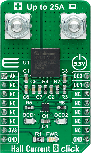
Hall Current 8 Click - 25A is based on the TLI4971-A025T5, a high-precision miniature coreless magnetic current sensor for AC and DC measurements with an analog interface and two fast overcurrent detection outputs from Infineon Technologies. The well-established Hall technology, on which the TLI4971 is based, enables accurate and highly linear measurement of currents with a full scale that depends on the chosen product variant, in this case, up to 25A. Typical applications are electrical drives and general-purpose inverters. It is suitable for fast over-current detection, which allows the control unit to switch off and protect the affected system from damage independently from the primary measurement path. The preconfigured output mode of the TLI4971-A025T5 is set to semi-differential mode. Current flowing through the
primary conductors is galvanically isolated, protecting low-voltage parts of the Click board™, as well as the host MCU, and induces a magnetic field that is differentially measured by two Hall probes. A high-performance amplifier combines the signal resulting from the differential field and the internal compensation information provided by the temperature and stress compensation unit. Then the amplifier output signal is fed into a differential output amplifier, which drives the sensor's analog output on the AN pin of the mikroBUS™ socket. In addition to the already mentioned characteristics, this Click board™ has two separate interface pins (OCD) routed to the PWM and INT pins of the mikroBUS socket. They provide fast output signals if a current exceeds a preset threshold in combination with the red and yellow LEDs marked
with OCD1 and OCD2. Thanks to independence from the main signal path, those pins offer a swift response. They can be used as a trap functionality to shut down the current source quickly and precisely detect mild overload conditions. Also, this Click board™ should be connected in series with the load. Two onboard terminal connectors measure the current, one terminal block for the positive and the other for the negative current input. This Click board™ can be operated only with a 3.3V logic voltage level. The board must perform appropriate logic voltage level conversion before using MCUs with different logic levels. Also, it comes equipped with a library containing functions and an example code that can be used, as a reference, for further development.


Features overview
Development board
Nucleo-64 with STM32F091RC MCU offers a cost-effective and adaptable platform for developers to explore new ideas and prototype their designs. This board harnesses the versatility of the STM32 microcontroller, enabling users to select the optimal balance of performance and power consumption for their projects. It accommodates the STM32 microcontroller in the LQFP64 package and includes essential components such as a user LED, which doubles as an ARDUINO® signal, alongside user and reset push-buttons, and a 32.768kHz crystal oscillator for precise timing operations. Designed with expansion and flexibility in mind, the Nucleo-64 board features an ARDUINO® Uno V3 expansion connector and ST morpho extension pin
headers, granting complete access to the STM32's I/Os for comprehensive project integration. Power supply options are adaptable, supporting ST-LINK USB VBUS or external power sources, ensuring adaptability in various development environments. The board also has an on-board ST-LINK debugger/programmer with USB re-enumeration capability, simplifying the programming and debugging process. Moreover, the board is designed to simplify advanced development with its external SMPS for efficient Vcore logic supply, support for USB Device full speed or USB SNK/UFP full speed, and built-in cryptographic features, enhancing both the power efficiency and security of projects. Additional connectivity is
provided through dedicated connectors for external SMPS experimentation, a USB connector for the ST-LINK, and a MIPI® debug connector, expanding the possibilities for hardware interfacing and experimentation. Developers will find extensive support through comprehensive free software libraries and examples, courtesy of the STM32Cube MCU Package. This, combined with compatibility with a wide array of Integrated Development Environments (IDEs), including IAR Embedded Workbench®, MDK-ARM, and STM32CubeIDE, ensures a smooth and efficient development experience, allowing users to fully leverage the capabilities of the Nucleo-64 board in their projects.

Microcontroller Overview
MCU Card / MCU

Architecture
ARM Cortex-M0
MCU Memory (KB)
256
Silicon Vendor
STMicroelectronics
Pin count
64
RAM (Bytes)
32768
You complete me!
Accessories
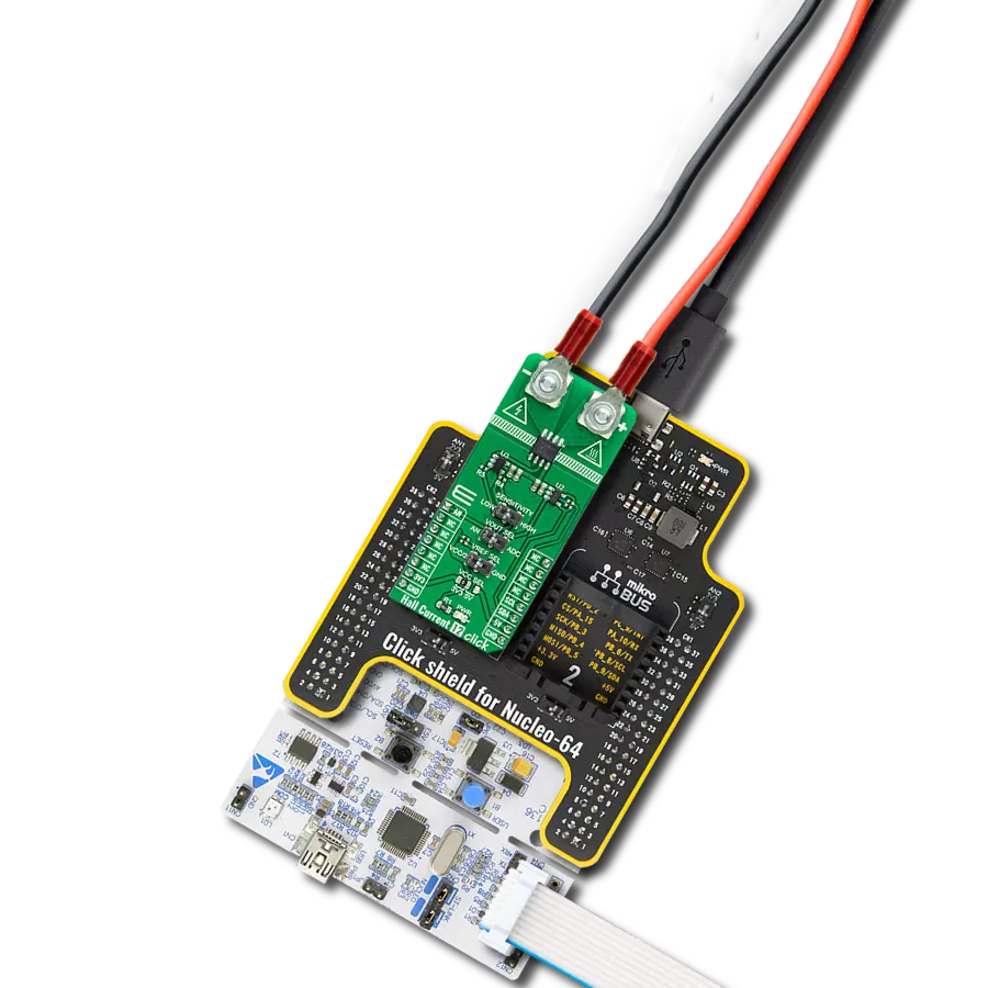
Click Shield for Nucleo-64 comes equipped with two proprietary mikroBUS™ sockets, allowing all the Click board™ devices to be interfaced with the STM32 Nucleo-64 board with no effort. This way, Mikroe allows its users to add any functionality from our ever-growing range of Click boards™, such as WiFi, GSM, GPS, Bluetooth, ZigBee, environmental sensors, LEDs, speech recognition, motor control, movement sensors, and many more. More than 1537 Click boards™, which can be stacked and integrated, are at your disposal. The STM32 Nucleo-64 boards are based on the microcontrollers in 64-pin packages, a 32-bit MCU with an ARM Cortex M4 processor operating at 84MHz, 512Kb Flash, and 96KB SRAM, divided into two regions where the top section represents the ST-Link/V2 debugger and programmer while the bottom section of the board is an actual development board. These boards are controlled and powered conveniently through a USB connection to program and efficiently debug the Nucleo-64 board out of the box, with an additional USB cable connected to the USB mini port on the board. Most of the STM32 microcontroller pins are brought to the IO pins on the left and right edge of the board, which are then connected to two existing mikroBUS™ sockets. This Click Shield also has several switches that perform functions such as selecting the logic levels of analog signals on mikroBUS™ sockets and selecting logic voltage levels of the mikroBUS™ sockets themselves. Besides, the user is offered the possibility of using any Click board™ with the help of existing bidirectional level-shifting voltage translators, regardless of whether the Click board™ operates at a 3.3V or 5V logic voltage level. Once you connect the STM32 Nucleo-64 board with our Click Shield for Nucleo-64, you can access hundreds of Click boards™, working with 3.3V or 5V logic voltage levels.

Used MCU Pins
mikroBUS™ mapper
Take a closer look
Click board™ Schematic

Step by step
Project assembly
Start by selecting your development board and Click board™. Begin with the Nucleo-64 with STM32F091RC MCU as your development board.


Track your results in real time
Application Output
1. Application Output - In Debug mode, the 'Application Output' window enables real-time data monitoring, offering direct insight into execution results. Ensure proper data display by configuring the environment correctly using the provided tutorial.

2. UART Terminal - Use the UART Terminal to monitor data transmission via a USB to UART converter, allowing direct communication between the Click board™ and your development system. Configure the baud rate and other serial settings according to your project's requirements to ensure proper functionality. For step-by-step setup instructions, refer to the provided tutorial.

3. Plot Output - The Plot feature offers a powerful way to visualize real-time sensor data, enabling trend analysis, debugging, and comparison of multiple data points. To set it up correctly, follow the provided tutorial, which includes a step-by-step example of using the Plot feature to display Click board™ readings. To use the Plot feature in your code, use the function: plot(*insert_graph_name*, variable_name);. This is a general format, and it is up to the user to replace 'insert_graph_name' with the actual graph name and 'variable_name' with the parameter to be displayed.

Software Support
Library Description
This library contains API for Hall Current 8 Click - 25A driver.
Key functions:
hallcurrent825a_calibration- This function sets the calibration value into the offset data from context object of the TLI4971 high precision coreless current sensor on Hall Current 8 25A Clickhallcurrent825a_get_voltage- This function reads results of AD conversion of the AN pin and converts them to proportional voltage levelhallcurrent825a_get_current- This function reads results of AD conversion of the AN pin and converts them to proportional current level
Open Source
Code example
The complete application code and a ready-to-use project are available through the NECTO Studio Package Manager for direct installation in the NECTO Studio. The application code can also be found on the MIKROE GitHub account.
/*!
* @file main.c
* @brief Hall Current 8 25A Click Example.
*
* # Description
* This library contains API for Hall Current 8 25A Click driver.
* The library initializes and defines the ADC drivers.
* The library also includes a function for calibration,
* current measurement and overcurrent detection.
*
* The demo application is composed of two sections :
*
* ## Application Init
* Initializes ADC driver, calibrate AD conversion of the AN pin and start to write log.
*
* ## Application Task
* This is an example that demonstrates the use of the Hall Current 8 25A Click board.
* In this example, we read and display current data [A], AN pin voltage level [V].
* Results are being sent to the Usart Terminal where you can track their changes.
*
* @author Stefan Ilic
*
*/
#include "board.h"
#include "log.h"
#include "hallcurrent825a.h"
static hallcurrent825a_t hallcurrent825a; /**< Hall Current 8 25A Click driver object. */
static log_t logger; /**< Logger object. */
void application_init ( void )
{
log_cfg_t log_cfg; /**< Logger config object. */
hallcurrent825a_cfg_t hallcurrent825a_cfg; /**< Click config object. */
/**
* Logger initialization.
* Default baud rate: 115200
* Default log level: LOG_LEVEL_DEBUG
* @note If USB_UART_RX and USB_UART_TX
* are defined as HAL_PIN_NC, you will
* need to define them manually for log to work.
* See @b LOG_MAP_USB_UART macro definition for detailed explanation.
*/
LOG_MAP_USB_UART( log_cfg );
log_init( &logger, &log_cfg );
log_info( &logger, " Application Init " );
// Click initialization.
hallcurrent825a_cfg_setup( &hallcurrent825a_cfg );
HALLCURRENT825A_MAP_MIKROBUS( hallcurrent825a_cfg, MIKROBUS_1 );
if ( ADC_ERROR == hallcurrent825a_init( &hallcurrent825a, &hallcurrent825a_cfg ) )
{
log_error( &logger, " Application Init Error. " );
log_info( &logger, " Please, run program again... " );
for ( ; ; );
}
Delay_ms ( 1000 );
log_printf( &logger, "---------------------------\r\n" );
log_printf( &logger, " Turn OFF the power supply \r\n" );
Delay_ms ( 1000 );
Delay_ms ( 1000 );
Delay_ms ( 1000 );
Delay_ms ( 1000 );
Delay_ms ( 1000 );
log_printf( &logger, "---------------------------\r\n" );
log_printf( &logger, " Start Calibration \r\n" );
hallcurrent825a_calibration ( &hallcurrent825a );
Delay_ms ( 1000 );
log_printf( &logger, "---------------------------\r\n");
log_printf( &logger, " Turn ON the power supply \r\n" );
Delay_ms ( 1000 );
Delay_ms ( 1000 );
Delay_ms ( 1000 );
Delay_ms ( 1000 );
Delay_ms ( 1000 );
log_printf( &logger, "---------------------------\r\n");
log_printf( &logger, " Start measurements : \r\n");
log_printf( &logger, "---------------------------\r\n");
}
void application_task ( void )
{
float current = 0;
float avg_voltage = 0;
if ( HALLCURRENT825A_OK == hallcurrent825a_get_current ( &hallcurrent825a, ¤t ) )
{
log_printf( &logger, " Current : %.2f [A]\r\n", current );
}
if ( HALLCURRENT825A_OK == hallcurrent825a_get_voltage ( &hallcurrent825a, &avg_voltage ) )
{
log_printf( &logger, " AN pin voltage : %.2f [V]\r\n", avg_voltage );
}
log_printf( &logger, "---------------------------\r\n");
Delay_ms ( 1000 );
}
int main ( void )
{
/* Do not remove this line or clock might not be set correctly. */
#ifdef PREINIT_SUPPORTED
preinit();
#endif
application_init( );
for ( ; ; )
{
application_task( );
}
return 0;
}
// ------------------------------------------------------------------------ END
Additional Support
Resources
Category:Current sensor