Switch and multiplex I2C signals with ease using TCA9543A and STM32F091RC
Simplify I2C connections
Published Feb 26, 2024
Click board™
I2C MUX 4 Click
Dev. board
Nucleo-64 with STM32F091RC MCU
Compiler
NECTO Studio
MCU
STM32F091RC
Elevate your I2C communication capabilities and unlock the full potential of your connected devices with our I2C multiplexer solution
A
A
Hardware Overview
How does it work?
I2C MUX 4 Click is based on the TCA9543A, a 2-channel, bidirectional translating I2C switch from Texas Instruments. The master SCL/SDA signal pair is directed to two channels of slave devices SC0/SD0 - SC1/SD1 where either individual channel or both channels can be selected determined by the programmable control register. The TCA9543A supports interrupt signals for the Master to detect an interrupt that can result from any of the slave devices connected to the interrupt pins on the output I2C channel header. It features I2C control using a single 8-bit control register in which bits 1 and 0 control the enabling and disabling of the two switch channels of I2C data flow, it supports a reset function, hot insertion, and has all switch channels deselected during Power-Up. This Click board™ includes a low dropout linear regulator
AP7331 from Diodes Incorporated to provide the 2.45V supply voltage for the TCA9543A. When the TCA9543APWR is turned on for the first time or anytime the device needs to be reset by cycling the power supply, which means that the Power-On reset requirements must be followed to ensure the I2C bus logic is initialized properly. The TCA9543APWR can also be reset to its default conditions by using the Power-On reset feature in the event of a glitch or data corruption. I2C MUX 4 Click communicates with MCU using the standard I2C 2-Wire interface that supports Standard-Mode (100 kHz) and Fast-Mode (400 kHz) operation. The TCA9543A generates a programmable interrupt signal routed on the INT pin of the mikroBUS™ used for the Master to detect an interrupt which can result from any of the slave devices
connected to the output I2C channel pins. It also has two address pins that allow the choice of the least significant bit (LSB) of its I2C slave address which can be done by using the SMD jumper labeled as ADDR SEL, and a Reset function routed on the RST pin of the mikroBUS™ socket used to recover the TCA9543A from a bus-fault condition. This Click board™ can operate with either 3.3V or 5V logic voltage levels selected via the VCC SEL jumper. This way, both 3.3V and 5V capable MCUs can use the communication lines properly. Also, this Click board™ comes equipped with a library containing easy-to-use functions and an example code that can be used as a reference for further development.


Features overview
Development board
Nucleo-64 with STM32F091RC MCU offers a cost-effective and adaptable platform for developers to explore new ideas and prototype their designs. This board harnesses the versatility of the STM32 microcontroller, enabling users to select the optimal balance of performance and power consumption for their projects. It accommodates the STM32 microcontroller in the LQFP64 package and includes essential components such as a user LED, which doubles as an ARDUINO® signal, alongside user and reset push-buttons, and a 32.768kHz crystal oscillator for precise timing operations. Designed with expansion and flexibility in mind, the Nucleo-64 board features an ARDUINO® Uno V3 expansion connector and ST morpho extension pin
headers, granting complete access to the STM32's I/Os for comprehensive project integration. Power supply options are adaptable, supporting ST-LINK USB VBUS or external power sources, ensuring adaptability in various development environments. The board also has an on-board ST-LINK debugger/programmer with USB re-enumeration capability, simplifying the programming and debugging process. Moreover, the board is designed to simplify advanced development with its external SMPS for efficient Vcore logic supply, support for USB Device full speed or USB SNK/UFP full speed, and built-in cryptographic features, enhancing both the power efficiency and security of projects. Additional connectivity is
provided through dedicated connectors for external SMPS experimentation, a USB connector for the ST-LINK, and a MIPI® debug connector, expanding the possibilities for hardware interfacing and experimentation. Developers will find extensive support through comprehensive free software libraries and examples, courtesy of the STM32Cube MCU Package. This, combined with compatibility with a wide array of Integrated Development Environments (IDEs), including IAR Embedded Workbench®, MDK-ARM, and STM32CubeIDE, ensures a smooth and efficient development experience, allowing users to fully leverage the capabilities of the Nucleo-64 board in their projects.

Microcontroller Overview
MCU Card / MCU

Architecture
ARM Cortex-M0
MCU Memory (KB)
256
Silicon Vendor
STMicroelectronics
Pin count
64
RAM (Bytes)
32768
You complete me!
Accessories
Click Shield for Nucleo-64 comes equipped with two proprietary mikroBUS™ sockets, allowing all the Click board™ devices to be interfaced with the STM32 Nucleo-64 board with no effort. This way, Mikroe allows its users to add any functionality from our ever-growing range of Click boards™, such as WiFi, GSM, GPS, Bluetooth, ZigBee, environmental sensors, LEDs, speech recognition, motor control, movement sensors, and many more. More than 1537 Click boards™, which can be stacked and integrated, are at your disposal. The STM32 Nucleo-64 boards are based on the microcontrollers in 64-pin packages, a 32-bit MCU with an ARM Cortex M4 processor operating at 84MHz, 512Kb Flash, and 96KB SRAM, divided into two regions where the top section represents the ST-Link/V2 debugger and programmer while the bottom section of the board is an actual development board. These boards are controlled and powered conveniently through a USB connection to program and efficiently debug the Nucleo-64 board out of the box, with an additional USB cable connected to the USB mini port on the board. Most of the STM32 microcontroller pins are brought to the IO pins on the left and right edge of the board, which are then connected to two existing mikroBUS™ sockets. This Click Shield also has several switches that perform functions such as selecting the logic levels of analog signals on mikroBUS™ sockets and selecting logic voltage levels of the mikroBUS™ sockets themselves. Besides, the user is offered the possibility of using any Click board™ with the help of existing bidirectional level-shifting voltage translators, regardless of whether the Click board™ operates at a 3.3V or 5V logic voltage level. Once you connect the STM32 Nucleo-64 board with our Click Shield for Nucleo-64, you can access hundreds of Click boards™, working with 3.3V or 5V logic voltage levels.

Used MCU Pins
mikroBUS™ mapper
Take a closer look
Click board™ Schematic

Step by step
Project assembly
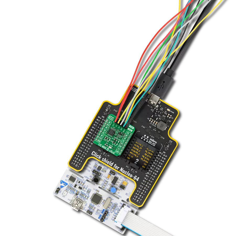
Start by selecting your development board and Click board™. Begin with the Nucleo-64 with STM32F091RC MCU as your development board.


Software Support
Library Description
This library contains API for I2C MUX 4 Click driver.
Key functions:
i2cmux4_get_ch_interrupt- Get channel interrupt functioni2cmux4_rmt_read_bytes- Generic read data functioni2cmux4_check_int- Check interrupt function.
Open Source
Code example
The complete application code and a ready-to-use project are available through the NECTO Studio Package Manager for direct installation in the NECTO Studio. The application code can also be found on the MIKROE GitHub account.
/*!
 * \file
 * \brief I2cMux4 Click example
 *
 * # Description
 * This example demonstrates the use of the I2C MUX 4 Click.
 *
 * The demo application is composed of two sections :
 *
 * ## Application Init
 * Initializes the driver, enables the Click board and makes an initial log.
 *
 * ## Application Task
 * In this example, we read the device ID register of the connected Click boards.
 * Channel 0 : 6DOF IMU 12 Click [slave address: 0x68; reg: 0x00; id val.: 0x24],
 * Channel 1 : Compass 3 Click   [slave address: 0x30; reg: 0x2F; id val.: 0x0C].
 * All data logs write on USB UART changes every 2 sec.
 *
 * \author MikroE Team
 *
 */
// ------------------------------------------------------------------- INCLUDES

#include "board.h"
#include "log.h"
#include "i2cmux4.h"

// ------------------------------------------------------------------ VARIABLES

static i2cmux4_t i2cmux4;
static log_t logger;

uint8_t rx_data;

// ------------------------------------------------------ APPLICATION FUNCTIONS

void application_init ( void )
{
    log_cfg_t log_cfg;
    i2cmux4_cfg_t cfg;

    /**
     * Logger initialization.
     * Default baud rate: 115200
     * Default log level: LOG_LEVEL_DEBUG
     * @note If USB_UART_RX and USB_UART_TX
     * are defined as HAL_PIN_NC, you will
     * need to define them manually for log to work.
     * See @b LOG_MAP_USB_UART macro definition for detailed explanation.
     */
    LOG_MAP_USB_UART( log_cfg );
    log_init( &logger, &log_cfg );
    log_info( &logger, "---- Application Init ----" );

    //  Click initialization.

    i2cmux4_cfg_setup( &cfg );
    I2CMUX4_MAP_MIKROBUS( cfg, MIKROBUS_1 );
    i2cmux4_init( &i2cmux4, &cfg );

    i2cmux4_power_on( &i2cmux4, I2CMUX4_ENABLE_POWER_ON );
    Delay_ms ( 100 );

    i2cmux4_set_channel( &i2cmux4, I2CMUX4_SEL_CH_ALL_DISABLE, 0x00 );
    Delay_ms ( 100 );
}

void application_task ( void )
{
    // CH 0 - 6DOF IMU 12 Click
    i2cmux4_set_channel( &i2cmux4, I2CMUX4_SEL_CH_0, 0x68 );
    Delay_ms ( 100 );

    i2cmux4_rmt_read_bytes( &i2cmux4, 0x00, &rx_data, 1 );
    Delay_ms ( 100 );

    log_printf( &logger, "    6DOF IMU 12 Click   \r\n" );
    log_printf( &logger, "- - - - - - - - - - - - \r\n" );
    log_printf( &logger, "       ID = 0x%.2X  \r\n", ( uint16_t ) rx_data );
    log_printf( &logger, "----------------------- \r\n" );
    Delay_ms ( 1000 );


    // CH 1 - Compass 3 Click
    i2cmux4_set_channel( &i2cmux4, I2CMUX4_SEL_CH_1, 0x30 );
    Delay_ms ( 100 );

    i2cmux4_rmt_read_bytes( &i2cmux4, 0x2F, &rx_data, 1 );
    Delay_ms ( 100 );

    log_printf( &logger, "      Compass 3 Click      \r\n" );
    log_printf( &logger, "- - - - - - - - - - - - \r\n" );
    log_printf( &logger, "       ID = 0x%.2X \r\n ", ( uint16_t ) rx_data );
    log_printf( &logger, "----------------------- \r\n" );
    Delay_ms ( 1000 );
}

int main ( void )
{
    /* Do not remove this line or clock might not be set correctly. */
    #ifdef PREINIT_SUPPORTED
    preinit();
    #endif

    application_init( );

    for ( ; ; )
    {
        application_task( );
    }

    return 0;
}

// ------------------------------------------------------------------------ END
Additional Support
Resources
Category:I2C


