Enjoy in various high-power lighting applications with TPS61160A and STM32F446RE
Shine brighter, last longer
Published Oct 08, 2024
Click board™
LED Driver 4 Click
Dev. board
Nucleo 64 with STM32F446RE MCU
Compiler
NECTO Studio
MCU
STM32F446RE
Experience enhanced efficiency and performance in your electronic designs by incorporating our reliable LED driver solution
A
A
Hardware Overview
How does it work?
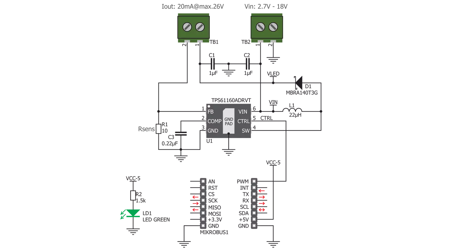
LED Driver 4 Click is based on the TPS61160A, a white LED driver with PWM brightness control, from Texas Instruments. The TPS61160A driver uses the boost converter topology with the current mode control. Its operation is very similar to a typical boost DC-DC converter with some additional features, useful for LED array driving. The Click board™ can provide up to 26V on the output terminals, after which the open LED sensing section will shut down the output stage MOSFET and the IC itself as a protection measure. This prevents the output voltage from exceeding the maximum ratings of the device in the case when the output LED is disconnected. The same will happen if the voltage at the feedback pin drops under 50% of its nominal value, 200 mV. The TPS61160A allows the PWM signal to be applied to its CTRL input, routed to the PWM pin of the mikroBUS™, labeled as CTL. The signal applied to this pin will modulate the feedback voltage on the FB pin, which, after being filtered through the LP filter, reduces the DC current on the output and through the LED array. This dimming technique will not produce any noise, as the DC current is scaled down, while the PWM is applied only to the internal feedback voltage. The PWM frequency should stay within 5 kHz to 100 kHz for optimum performance. The current through the LED
segments is sensed via the onboard resistor connected between the GND and the FB pin. It is chosen so that the maximum LED current is 20 mA. This is the optimal current for the white LEDs, providing the maximum brightness without LED deterioration. Note that while this is true for most of the white LEDs, the datasheet of the particular LEDs used with the LED Driver 4 click should be checked for the forward current parameter. It should be at least 20 mA. As explained above, the dimming function will reduce this current, resulting in a dimmer LED light. A soft-start function is built into the device, and it slowly ramps the voltage at the FB pin, resulting in a slow increase of the output voltage over about 6 ms, preventing high inrush currents. The internal current limit is also set to half the maximum current specification for the first 5 ms of operation. Applying the LOW logic level to the CTL pin for more than 2.5 ms will put the device into Shutdown mode. While in Shutdown mode, the current consumption is minimal. However, a current path still exists through the inductor and the Schottky diode. To prevent unwanted activation of the LED array, the minimum forward voltage of the LED array should be above the input voltage. The power supply for the LED array is connected via the VIN screw terminal, allowing an
external power source to be used. The rating of the external power source should stay within the range of 2V to 18V. The second screw terminal with the LED icon underneath connects the LED array. The maximum forward voltage of the LED array should stay below the device's minimum overprotection voltage, typically 25V. The maximum forward voltage of the LED element depends on the used LED type. It can be found in the datasheet of the used LED. The minimum overprotection voltage of the TPS61160A IC can be found in the TPS61160A, but it is also available in the Electrical Characteristics table below. Click board™ itself is powered via 5V mikroBUS™ rail. However, the Click board™ allows both 3.3V and 5V MCUs to drive its CTL input, as long as the voltage for the LOW logic level stays under 0.4V and the voltage for the HIGH logic level applied to this pin stays above 1.2V. The use of the Led Driver 4 click is easy and straightforward. However, MikroElektronika provides a library that contains functions compatible with the MikroElektronika compilers, which can be used for simplified LED array driving. The library also contains an example application that demonstrates their use. This example application can be used as a reference for custom designs.

Features overview
Development board
Nucleo-64 with STM32F446RE MCU offers a cost-effective and adaptable platform for developers to explore new ideas and prototype their designs. This board harnesses the versatility of the STM32 microcontroller, enabling users to select the optimal balance of performance and power consumption for their projects. It accommodates the STM32 microcontroller in the LQFP64 package and includes essential components such as a user LED, which doubles as an ARDUINO® signal, alongside user and reset push-buttons, and a 32.768kHz crystal oscillator for precise timing operations. Designed with expansion and flexibility in mind, the Nucleo-64 board features an ARDUINO® Uno V3 expansion connector and ST morpho extension pin
headers, granting complete access to the STM32's I/Os for comprehensive project integration. Power supply options are adaptable, supporting ST-LINK USB VBUS or external power sources, ensuring adaptability in various development environments. The board also has an on-board ST-LINK debugger/programmer with USB re-enumeration capability, simplifying the programming and debugging process. Moreover, the board is designed to simplify advanced development with its external SMPS for efficient Vcore logic supply, support for USB Device full speed or USB SNK/UFP full speed, and built-in cryptographic features, enhancing both the power efficiency and security of projects. Additional connectivity is
provided through dedicated connectors for external SMPS experimentation, a USB connector for the ST-LINK, and a MIPI® debug connector, expanding the possibilities for hardware interfacing and experimentation. Developers will find extensive support through comprehensive free software libraries and examples, courtesy of the STM32Cube MCU Package. This, combined with compatibility with a wide array of Integrated Development Environments (IDEs), including IAR Embedded Workbench®, MDK-ARM, and STM32CubeIDE, ensures a smooth and efficient development experience, allowing users to fully leverage the capabilities of the Nucleo-64 board in their projects.

Microcontroller Overview
MCU Card / MCU

Architecture
ARM Cortex-M4
MCU Memory (KB)
512
Silicon Vendor
STMicroelectronics
Pin count
64
RAM (Bytes)
131072
You complete me!
Accessories
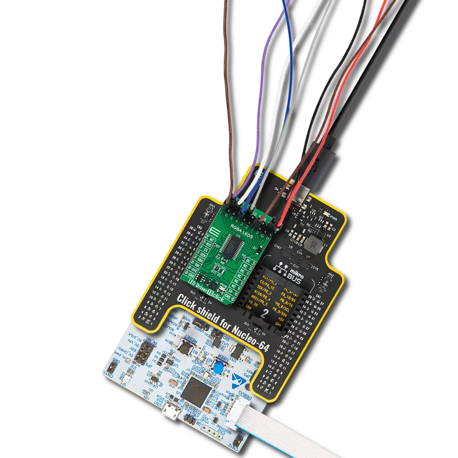
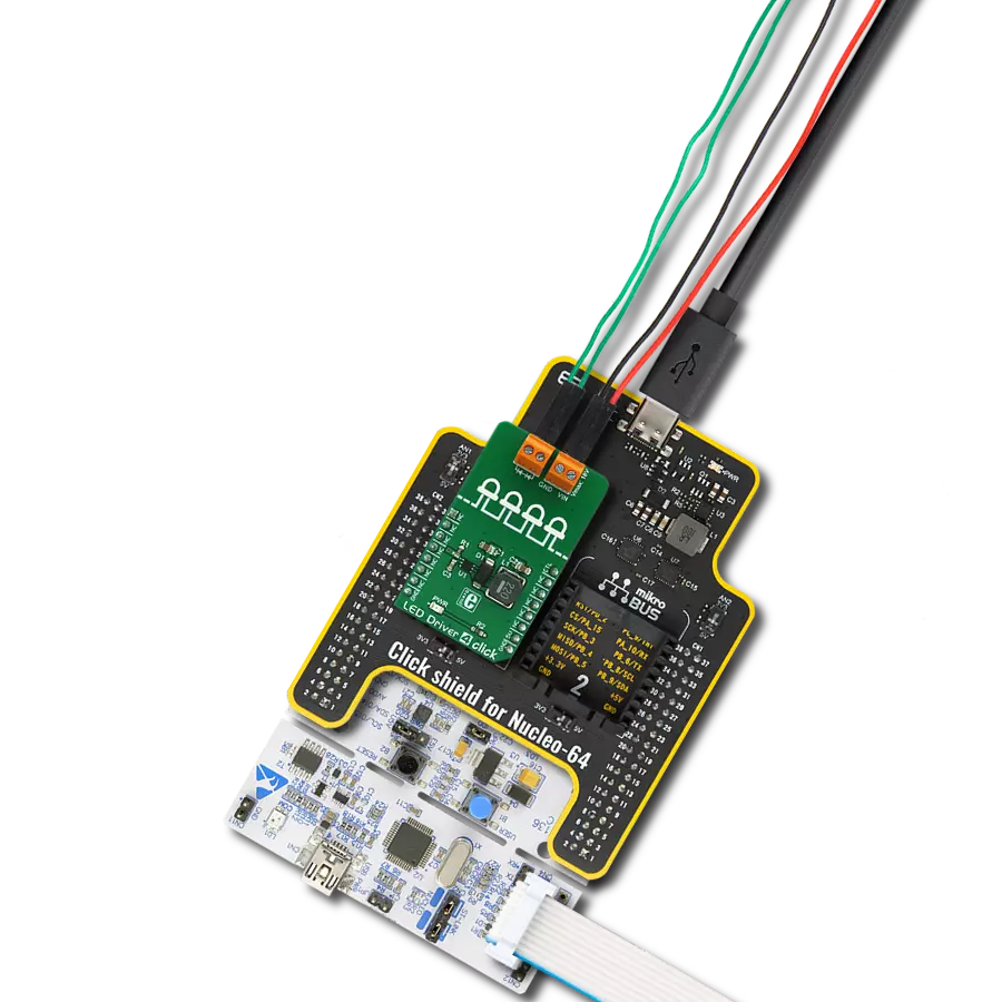
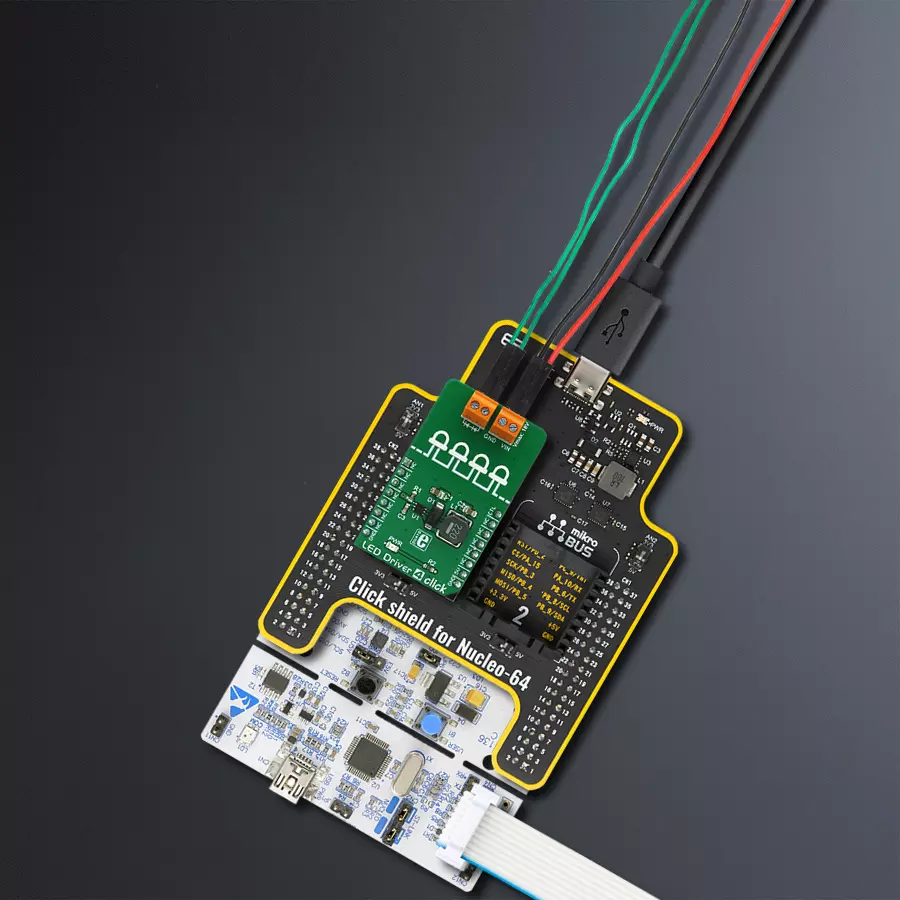
Click Shield for Nucleo-64 comes equipped with two proprietary mikroBUS™ sockets, allowing all the Click board™ devices to be interfaced with the STM32 Nucleo-64 board with no effort. This way, Mikroe allows its users to add any functionality from our ever-growing range of Click boards™, such as WiFi, GSM, GPS, Bluetooth, ZigBee, environmental sensors, LEDs, speech recognition, motor control, movement sensors, and many more. More than 1537 Click boards™, which can be stacked and integrated, are at your disposal. The STM32 Nucleo-64 boards are based on the microcontrollers in 64-pin packages, a 32-bit MCU with an ARM Cortex M4 processor operating at 84MHz, 512Kb Flash, and 96KB SRAM, divided into two regions where the top section represents the ST-Link/V2 debugger and programmer while the bottom section of the board is an actual development board. These boards are controlled and powered conveniently through a USB connection to program and efficiently debug the Nucleo-64 board out of the box, with an additional USB cable connected to the USB mini port on the board. Most of the STM32 microcontroller pins are brought to the IO pins on the left and right edge of the board, which are then connected to two existing mikroBUS™ sockets. This Click Shield also has several switches that perform functions such as selecting the logic levels of analog signals on mikroBUS™ sockets and selecting logic voltage levels of the mikroBUS™ sockets themselves. Besides, the user is offered the possibility of using any Click board™ with the help of existing bidirectional level-shifting voltage translators, regardless of whether the Click board™ operates at a 3.3V or 5V logic voltage level. Once you connect the STM32 Nucleo-64 board with our Click Shield for Nucleo-64, you can access hundreds of Click boards™, working with 3.3V or 5V logic voltage levels.

Used MCU Pins
mikroBUS™ mapper
Take a closer look
Click board™ Schematic
Step by step
Project assembly
Start by selecting your development board and Click board™. Begin with the Nucleo 64 with STM32F446RE MCU as your development board.


Track your results in real time
Application Output
1. Application Output - In Debug mode, the 'Application Output' window enables real-time data monitoring, offering direct insight into execution results. Ensure proper data display by configuring the environment correctly using the provided tutorial.

2. UART Terminal - Use the UART Terminal to monitor data transmission via a USB to UART converter, allowing direct communication between the Click board™ and your development system. Configure the baud rate and other serial settings according to your project's requirements to ensure proper functionality. For step-by-step setup instructions, refer to the provided tutorial.

3. Plot Output - The Plot feature offers a powerful way to visualize real-time sensor data, enabling trend analysis, debugging, and comparison of multiple data points. To set it up correctly, follow the provided tutorial, which includes a step-by-step example of using the Plot feature to display Click board™ readings. To use the Plot feature in your code, use the function: plot(*insert_graph_name*, variable_name);. This is a general format, and it is up to the user to replace 'insert_graph_name' with the actual graph name and 'variable_name' with the parameter to be displayed.

Software Support
Library Description
This library contains API for LED Driver 4 Click driver.
Key functions:
leddriver4_set_duty_cycle- Generic sets PWM duty cycleleddriver4_pwm_stop- Stop PWM moduleleddriver4_pwm_start- Start PWM module.
Open Source
Code example
The complete application code and a ready-to-use project are available through the NECTO Studio Package Manager for direct installation in the NECTO Studio. The application code can also be found on the MIKROE GitHub account.
/*!
 * @file
 * @brief LedDriver4 Click example
 *
 * # Description
 * This Click has the ability to dim the connected LED array, without producing any noise on the output.
 *
 * The demo application is composed of two sections :
 *
 * ## Application Init
 * Initializes the GPIO driver and
 * configures the PWM peripheral for controlling the LED array intensity.
 *
 * ## Application Task
 * Increases and decreases LED array intensity
 * ( first increases light intensity to the maximum and then decreases to the minimum ).
 * Results are being sent to the Usart Terminal where you can track their changes.
 *
 *
 * @author Nikola Peric
 *
 */
// ------------------------------------------------------------------- INCLUDES

#include "board.h"
#include "log.h"
#include "leddriver4.h"

// ------------------------------------------------------------------ VARIABLES

static leddriver4_t leddriver4;
static log_t logger;

// ------------------------------------------------------ APPLICATION FUNCTIONS

void application_init ( void )
{
    log_cfg_t log_cfg;
    leddriver4_cfg_t cfg;

    /**
     * Logger initialization.
     * Default baud rate: 115200
     * Default log level: LOG_LEVEL_DEBUG
     * @note If USB_UART_RX and USB_UART_TX
     * are defined as HAL_PIN_NC, you will
     * need to define them manually for log to work.
     * See @b LOG_MAP_USB_UART macro definition for detailed explanation.
     */
    LOG_MAP_USB_UART( log_cfg );
    log_init( &logger, &log_cfg );
    log_info( &logger, "---- Application Init ----" );

    //  Click initialization.

    leddriver4_cfg_setup( &cfg );
    LEDDRIVER4_MAP_MIKROBUS( cfg, MIKROBUS_1 );
    leddriver4_init( &leddriver4, &cfg );

    leddriver4_set_duty_cycle ( &leddriver4, 0.0 );
    leddriver4_pwm_start( &leddriver4 );
    log_info( &logger, "---- Application Task ----" );
    Delay_ms ( 500 );
}

void application_task ( void )
{
    static int8_t duty_cnt = 1;
    static int8_t duty_inc = 1;
    float duty = duty_cnt / 10.0;

    leddriver4_set_duty_cycle ( &leddriver4, duty );
    log_printf( &logger, "Duty: %d%%\r\n", ( uint16_t )( duty_cnt * 10 ) );
    Delay_ms ( 500 );

    if ( 10 == duty_cnt )
    {
        duty_inc = -1;
    }
    else if ( 0 == duty_cnt )
    {
        duty_inc = 1;
    }
    duty_cnt += duty_inc;
}

int main ( void )
{
    /* Do not remove this line or clock might not be set correctly. */
    #ifdef PREINIT_SUPPORTED
    preinit();
    #endif

    application_init( );

    for ( ; ; )
    {
        application_task( );
    }

    return 0;
}


// ------------------------------------------------------------------------ END
Additional Support
Resources
Category:LED Drivers