Increase accuracy and reliability in global positioning across different regions and conditions with Mosaic-x5 and STM32F091RC
Compact global navigation satellite system (GNSS) receiver

Published Apr 09, 2024
Click board™
Mosaic Click
Dev. board
Nucleo-64 with STM32F091RC MCU
Compiler
NECTO Studio
MCU
STM32F091RC
Provide precise navigation and location-based applications through high-quality global positioning, using multi-band and multi-constellation GNSS satellite signal tracking
A
A
Hardware Overview
How does it work?
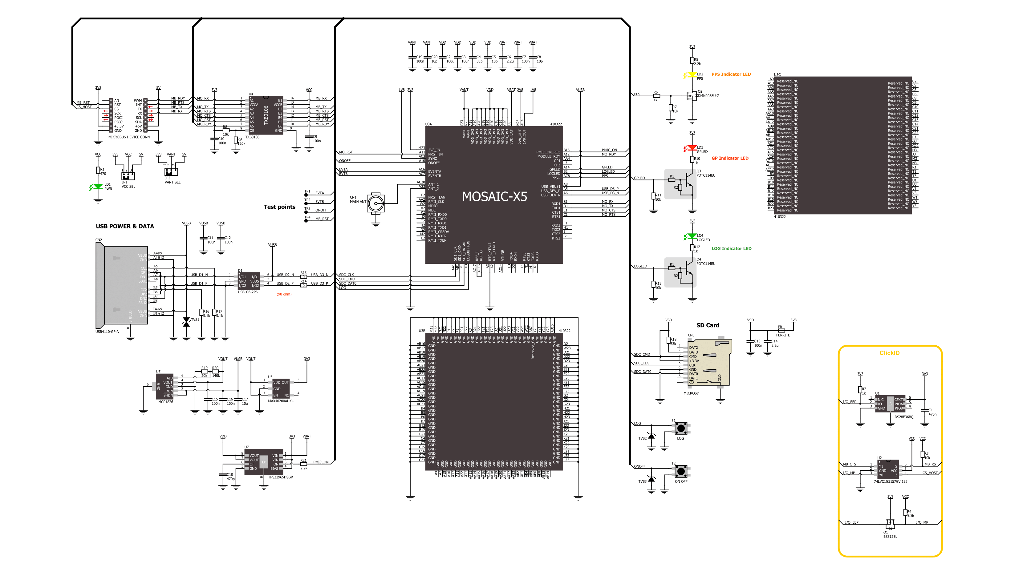
Mosaic Click is based on the Mosaic-X5, a compact GNSS receiver from Septentrio. This receiver offers centimeter-level accuracy across multiple bands and satellite constellations such as GPS, GLONASS, Beidou, Galileo, and NavIC. It integrates AIM+ technology for advanced interference mitigation and anti-spoofing, providing unmatched reliability and precision. This technology can neutralize diverse signal interferences, ranging from simple, continuous narrowband signals to complex wideband and pulsed jammers. Designed for mass-market applications like robotics and autonomous technologies, this solution not only ensures low power consumption but also offers a wide range of interface options and delivers RTK positioning. Communication between the Mosaic-X5 and the host MCU is made through a UART interface, using the standard UART RX and TX pins and hardware flow control pins (CTS/RTS). The module communicates at 115200bps by default, allowing efficient data exchange. This Click board™ also incorporates a reset pin (RST) for direct module resetting and a ready indicator (RDY) that signals the module's operational status through logical high
(active) or low (standby or reset) states. Furthermore, the module supports USB connectivity in device mode, adhering to the USB 2.0 standard for high-speed data transfers (up to 480Mbps). It includes options for USB power achieved by an LDO (the MCP1826) or an alternative power switch (the TPS22965), each ensuring the required 3.3V for normal module operation. In addition to the USB interface, it is also equipped with a microSD card slot for external data logging, which can be controlled via a LOG button. This button enables the toggling of SD card logging and manages the card's mounting status, which can be monitored through a green LED indicator marked LOG. If the LOG button is pressed for 100ms to 5 seconds, it toggles SD Card logging ON and OFF. Holding this button for more than 5 seconds and then releasing it unmounts the SD card if it is mounted, and vice versa. The green LOG LED indicator can check the SD card mount status. In addition to the LOG LED, the board also features a general-purpose user-configurable red LED, a yellow PPS (Pulse Per Second) LED, and four test points. TP1 and TP2 are two event timers that can be used to time tag external events with a
time resolution of 20ns, while TR3 and TP4 present the same functions as ON/OFF and Reset features. It is also possible to power off the module with the ON/OFF button and to toggle it between active and standby mode. However, this abrupt power interruption could cause data losses when logging on an external SD card. The board features a u.Fl connector for a GNSS antenna, like the GNSS Active External Antenna that MIKROE offers, in combination with an IPEX-SMA cable for flexible and efficient connectivity options. In addition, the user can easily choose the external antenna's power supply by choosing between 3.3V and 5V on the VANT SEL jumper. This Click board™ can operate with both 3.3V and 5V logic voltage levels selected via the VCC SEL jumper. Given that the Mosaic-X5 module operates at 3.3V, a logic-level translator, TXB0106, is also used for proper operation and an accurate signal-level translation. This way, both 3.3V and 5V capable MCUs can use the communication lines properly. Also, this Click board™ comes equipped with a library containing easy-to-use functions and an example code that can be used as a reference for further development.

Features overview
Development board
Nucleo-64 with STM32F091RC MCU offers a cost-effective and adaptable platform for developers to explore new ideas and prototype their designs. This board harnesses the versatility of the STM32 microcontroller, enabling users to select the optimal balance of performance and power consumption for their projects. It accommodates the STM32 microcontroller in the LQFP64 package and includes essential components such as a user LED, which doubles as an ARDUINO® signal, alongside user and reset push-buttons, and a 32.768kHz crystal oscillator for precise timing operations. Designed with expansion and flexibility in mind, the Nucleo-64 board features an ARDUINO® Uno V3 expansion connector and ST morpho extension pin
headers, granting complete access to the STM32's I/Os for comprehensive project integration. Power supply options are adaptable, supporting ST-LINK USB VBUS or external power sources, ensuring adaptability in various development environments. The board also has an on-board ST-LINK debugger/programmer with USB re-enumeration capability, simplifying the programming and debugging process. Moreover, the board is designed to simplify advanced development with its external SMPS for efficient Vcore logic supply, support for USB Device full speed or USB SNK/UFP full speed, and built-in cryptographic features, enhancing both the power efficiency and security of projects. Additional connectivity is
provided through dedicated connectors for external SMPS experimentation, a USB connector for the ST-LINK, and a MIPI® debug connector, expanding the possibilities for hardware interfacing and experimentation. Developers will find extensive support through comprehensive free software libraries and examples, courtesy of the STM32Cube MCU Package. This, combined with compatibility with a wide array of Integrated Development Environments (IDEs), including IAR Embedded Workbench®, MDK-ARM, and STM32CubeIDE, ensures a smooth and efficient development experience, allowing users to fully leverage the capabilities of the Nucleo-64 board in their projects.

Microcontroller Overview
MCU Card / MCU

Architecture
ARM Cortex-M0
MCU Memory (KB)
256
Silicon Vendor
STMicroelectronics
Pin count
64
RAM (Bytes)
32768
You complete me!
Accessories
Click Shield for Nucleo-64 comes equipped with two proprietary mikroBUS™ sockets, allowing all the Click board™ devices to be interfaced with the STM32 Nucleo-64 board with no effort. This way, Mikroe allows its users to add any functionality from our ever-growing range of Click boards™, such as WiFi, GSM, GPS, Bluetooth, ZigBee, environmental sensors, LEDs, speech recognition, motor control, movement sensors, and many more. More than 1537 Click boards™, which can be stacked and integrated, are at your disposal. The STM32 Nucleo-64 boards are based on the microcontrollers in 64-pin packages, a 32-bit MCU with an ARM Cortex M4 processor operating at 84MHz, 512Kb Flash, and 96KB SRAM, divided into two regions where the top section represents the ST-Link/V2 debugger and programmer while the bottom section of the board is an actual development board. These boards are controlled and powered conveniently through a USB connection to program and efficiently debug the Nucleo-64 board out of the box, with an additional USB cable connected to the USB mini port on the board. Most of the STM32 microcontroller pins are brought to the IO pins on the left and right edge of the board, which are then connected to two existing mikroBUS™ sockets. This Click Shield also has several switches that perform functions such as selecting the logic levels of analog signals on mikroBUS™ sockets and selecting logic voltage levels of the mikroBUS™ sockets themselves. Besides, the user is offered the possibility of using any Click board™ with the help of existing bidirectional level-shifting voltage translators, regardless of whether the Click board™ operates at a 3.3V or 5V logic voltage level. Once you connect the STM32 Nucleo-64 board with our Click Shield for Nucleo-64, you can access hundreds of Click boards™, working with 3.3V or 5V logic voltage levels.

GNSS Active External Antenna is a unique multi-band type of antenna coming from u-blox that is the perfect selection for high precision GNSS applications, which require highly accurate location abilities such as RTK. The ANN-MB-00 is a multi-band (L1, L2/E5b/B2I) active GNSS antenna with a 5m cable and SMA connector. The antenna supports GPS, GLONASS, Galileo, and BeiDou and includes a high-performance multi-band RHCP dual-feed patch antenna element, a built-in high-gain LNA with SAW pre-filtering, and a 5 m antenna cable with SMA connector, and is waterproof.

Used MCU Pins
mikroBUS™ mapper
Take a closer look
Click board™ Schematic
Step by step
Project assembly
Start by selecting your development board and Click board™. Begin with the Nucleo-64 with STM32F091RC MCU as your development board.


Track your results in real time
Application Output
1. Application Output - In Debug mode, the 'Application Output' window enables real-time data monitoring, offering direct insight into execution results. Ensure proper data display by configuring the environment correctly using the provided tutorial.

2. UART Terminal - Use the UART Terminal to monitor data transmission via a USB to UART converter, allowing direct communication between the Click board™ and your development system. Configure the baud rate and other serial settings according to your project's requirements to ensure proper functionality. For step-by-step setup instructions, refer to the provided tutorial.

3. Plot Output - The Plot feature offers a powerful way to visualize real-time sensor data, enabling trend analysis, debugging, and comparison of multiple data points. To set it up correctly, follow the provided tutorial, which includes a step-by-step example of using the Plot feature to display Click board™ readings. To use the Plot feature in your code, use the function: plot(*insert_graph_name*, variable_name);. This is a general format, and it is up to the user to replace 'insert_graph_name' with the actual graph name and 'variable_name' with the parameter to be displayed.

Software Support
Library Description
This library contains API for Mosaic Click driver.
Key functions:
mosaic_generic_read- This function reads a desired number of data bytes by using UART serial interfacemosaic_enable_nmea_output- This function enables the NMEA output with the selected message parameters and an output intervalmosaic_parse_gga- This function parses the GGA data from the read response buffer
Open Source
Code example
The complete application code and a ready-to-use project are available through the NECTO Studio Package Manager for direct installation in the NECTO Studio. The application code can also be found on the MIKROE GitHub account.
/*!
 * @file main.c
 * @brief Mosaic Click Example.
 *
 * # Description
 * This example demonstrates the use of Mosaic Click by reading and displaying
 * the GNSS coordinates.
 *
 * The demo application is composed of two sections :
 *
 * ## Application Init
 * Initializes the driver, reads the NMEA version, and enables the NMEA output.
 *
 * ## Application Task
 * Reads the received data, parses the NMEA GGA info from it, and once it receives
 * the position fix it will start displaying the coordinates on the USB UART.
 *
 * ## Additional Function
 * - static void mosaic_clear_app_buf ( void )
 * - static void mosaic_log_app_buf ( void )
 * - static err_t mosaic_process ( mosaic_t *ctx )
 * - static err_t mosaic_wait_prompt ( mosaic_t *ctx )
 * - static void mosaic_parser_application ( uint8_t *rsp )
 *
 * @author Stefan Filipovic
 *
 */

#include "board.h"
#include "log.h"
#include "mosaic.h"

// Application buffer size
#define APP_BUFFER_SIZE             500
#define PROCESS_BUFFER_SIZE         200

static mosaic_t mosaic;
static log_t logger;

static uint8_t app_buf[ APP_BUFFER_SIZE ] = { 0 };
static int32_t app_buf_len = 0;

/**
 * @brief Mosaic clearing application buffer.
 * @details This function clears memory of application buffer and reset its length.
 * @note None.
 */
static void mosaic_clear_app_buf ( void );

/**
 * @brief Mosaic log application buffer.
 * @details This function logs data from application buffer to USB UART.
 * @note None.
 */
static void mosaic_log_app_buf ( void );

/**
 * @brief Mosaic data reading function.
 * @details This function reads data from device and concatenates data to application buffer.
 * @param[in] ctx : Click context object.
 * See #mosaic_t object definition for detailed explanation.
 * @return @li @c  0 - Read some data.
 *         @li @c -1 - Nothing is read.
 * See #err_t definition for detailed explanation.
 * @note None.
 */
static err_t mosaic_process ( mosaic_t *ctx );

/**
 * @brief Mosaic wait prompt function.
 * @details This function waits for a "COM1>" prompt string to appear on UART which indicates
 * the device is ready to receive commands.
 * @param[in] ctx : Click context object.
 * See #mosaic_t object definition for detailed explanation.
 * @return @li @c  0 - Prompt (COM1>) read successfully.
 *         @li @c -2 - Timeout error.
 * See #err_t definition for detailed explanation.
 * @note None.
 */
static err_t mosaic_wait_prompt ( mosaic_t *ctx );

/**
 * @brief Mosaic parser application.
 * @param[in] rsp Response buffer.
 * @details This function logs GNSS data on the USB UART.
 * @return None.
 * @note None.
 */
static void mosaic_parser_application ( uint8_t *rsp );

void application_init ( void )
{
    log_cfg_t log_cfg;  /**< Logger config object. */
    mosaic_cfg_t mosaic_cfg;  /**< Click config object. */

    /**
     * Logger initialization.
     * Default baud rate: 115200
     * Default log level: LOG_LEVEL_DEBUG
     * @note If USB_UART_RX and USB_UART_TX
     * are defined as HAL_PIN_NC, you will
     * need to define them manually for log to work.
     * See @b LOG_MAP_USB_UART macro definition for detailed explanation.
     */
    LOG_MAP_USB_UART( log_cfg );
    log_init( &logger, &log_cfg );
    log_info( &logger, " Application Init " );

    // Click initialization.
    mosaic_cfg_setup( &mosaic_cfg );
    MOSAIC_MAP_MIKROBUS( mosaic_cfg, MIKROBUS_1 );
    if ( UART_ERROR == mosaic_init( &mosaic, &mosaic_cfg ) )
    {
        log_error( &logger, " Communication init." );
        for ( ; ; );
    }

    if ( MOSAIC_OK != mosaic_wait_prompt( &mosaic ) )
    {
        log_error( &logger, " No connection prompt detected." );
        for ( ; ; );
    }
    mosaic_log_app_buf( );
    mosaic_clear_app_buf( );
    Delay_ms ( 100 );

    mosaic_send_cmd( &mosaic, MOSAIC_CMD_GET_NMEA_VERSION );
    mosaic_wait_prompt( &mosaic );
    mosaic_log_app_buf( );
    mosaic_clear_app_buf( );
    Delay_ms ( 100 );

    mosaic_enable_nmea_output( &mosaic, MOSAIC_SNO_MESSAGES_GGA, MOSAIC_SNO_INTERVAL_SEC1 );
    mosaic_wait_prompt( &mosaic );
    mosaic_log_app_buf( );
    mosaic_clear_app_buf( );
    Delay_ms ( 100 );

    log_info( &logger, " Application Task " );
}

void application_task ( void )
{
    mosaic_process( &mosaic );
    if ( app_buf_len > ( sizeof ( MOSAIC_NMEA_GGA ) + MOSAIC_GGA_ELEMENT_SIZE ) )
    {
        mosaic_parser_application( app_buf );
    }
}

int main ( void )
{
    /* Do not remove this line or clock might not be set correctly. */
    #ifdef PREINIT_SUPPORTED
    preinit();
    #endif

    application_init( );

    for ( ; ; )
    {
        application_task( );
    }

    return 0;
}

static void mosaic_clear_app_buf ( void )
{
    memset( app_buf, 0, app_buf_len );
    app_buf_len = 0;
}

static void mosaic_log_app_buf ( void )
{
    for ( int32_t buf_cnt = 0; buf_cnt < app_buf_len; buf_cnt++ )
    {
        log_printf( &logger, "%c", app_buf[ buf_cnt ] );
    }
    log_printf( &logger, "\r\n" );
}

static err_t mosaic_process ( mosaic_t *ctx )
{
    uint8_t rx_buf[ PROCESS_BUFFER_SIZE ] = { 0 };
    int32_t overflow_bytes = 0;
    int32_t rx_cnt = 0;
    int32_t rx_size = mosaic_generic_read( ctx, rx_buf, PROCESS_BUFFER_SIZE );
    if ( ( rx_size > 0 ) && ( rx_size <= APP_BUFFER_SIZE ) )
    {
        if ( ( app_buf_len + rx_size ) > APP_BUFFER_SIZE )
        {
            overflow_bytes = ( app_buf_len + rx_size ) - APP_BUFFER_SIZE;
            app_buf_len = APP_BUFFER_SIZE - rx_size;
            memmove ( app_buf, &app_buf[ overflow_bytes ], app_buf_len );
            memset ( &app_buf[ app_buf_len ], 0, overflow_bytes );
        }
        for ( rx_cnt = 0; rx_cnt < rx_size; rx_cnt++ )
        {
            if ( rx_buf[ rx_cnt ] )
            {
                app_buf[ app_buf_len++ ] = rx_buf[ rx_cnt ];
            }
        }
        return MOSAIC_OK;
    }
    return MOSAIC_ERROR;
}

static err_t mosaic_wait_prompt ( mosaic_t *ctx )
{
    uint32_t timeout_cnt = 0;
    uint32_t timeout = 120000;
    mosaic_process( ctx );
    while ( 0 == strstr( app_buf, MOSAIC_PROMPT_CMD ) )
    {
        mosaic_process( ctx );
        if ( timeout_cnt++ > timeout )
        {
            mosaic_clear_app_buf( );
            return MOSAIC_ERROR_TIMEOUT;
        }
        Delay_ms ( 1 );
    }
    return MOSAIC_OK;
}

static void mosaic_parser_application ( uint8_t *rsp )
{
    uint8_t element_buf[ 100 ] = { 0 };
    if ( MOSAIC_OK == mosaic_parse_gga( rsp, MOSAIC_GGA_LATITUDE, element_buf ) )
    {
        static uint8_t wait_for_fix_cnt = 0;
        if ( strlen( element_buf ) > 0 )
        {
            log_printf( &logger, "\r\n Latitude: %.2s degrees, %s minutes \r\n", element_buf, &element_buf[ 2 ] );
            memset( element_buf, 0, sizeof( element_buf ) );
            mosaic_parse_gga( rsp, MOSAIC_GGA_LONGITUDE, element_buf );
            log_printf( &logger, " Longitude: %.3s degrees, %s minutes \r\n", element_buf, &element_buf[ 3 ] );
            memset( element_buf, 0, sizeof( element_buf ) );
            mosaic_parse_gga( rsp, MOSAIC_GGA_ALTITUDE, element_buf );
            log_printf( &logger, " Altitude: %s m \r\n", element_buf );
            wait_for_fix_cnt = 0;
        }
        else
        {
            if ( wait_for_fix_cnt % 5 == 0 )
            {
                log_printf( &logger, " Waiting for the position fix...\r\n\n" );
                wait_for_fix_cnt = 0;
            }
            wait_for_fix_cnt++;
        }
        mosaic_clear_app_buf(  );
    }
}

// ------------------------------------------------------------------------ END
Additional Support
Resources
Category:GPS/GNSS


