Add a knob and visual feedback to electronic projects with TLC5925 and STM32F410RB
Create visual effects and indicators in various applications

Published Oct 08, 2024
Click board™
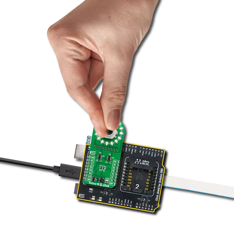
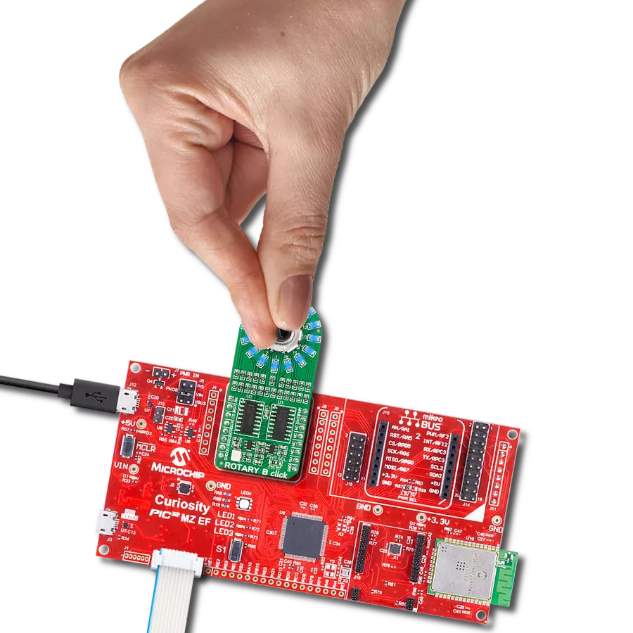
Rotary W 2 Click
Dev. board
Nucleo 64 with STM32F410RB MCU
Compiler
NECTO Studio
MCU
STM32F410RB
Enhance electronic designs by providing a precision input knob with visual feedback through a ring of 16 white LEDs
A
A
Hardware Overview
How does it work?
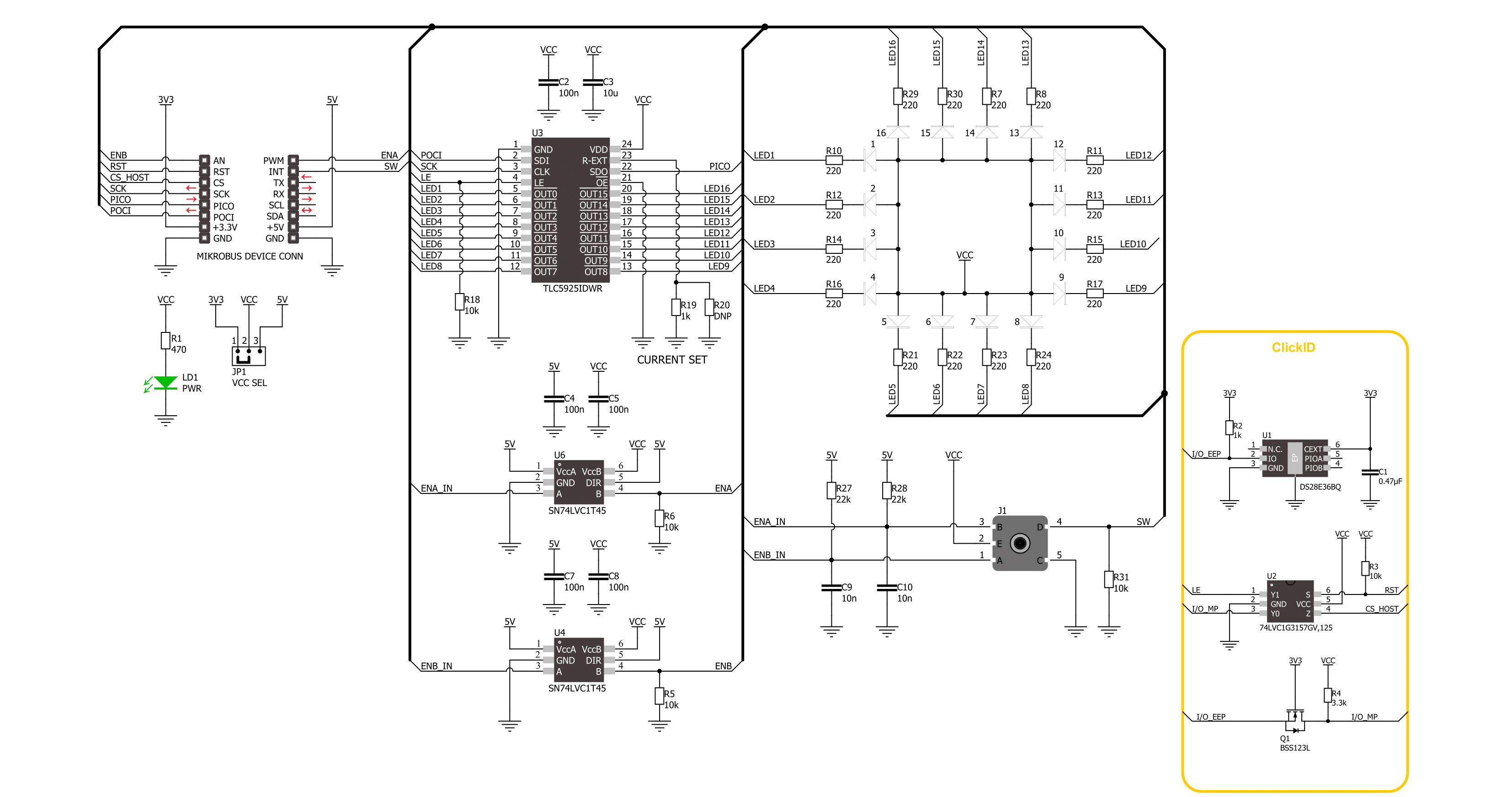
Rotary W 2 Click is based on the TLC5925, a low-power 16-channel constant-current LED sink driver from Texas Instruments that, combined with a high-quality rotary encoder from ALPS, the EC12D1564402, allows you to add a precision input knob to your design. The EC12D1564402 incremental rotary encoder is surrounded by a ring of 16 green LEDs where a single rotation is divided into 15 discrete steps (in contrast to a potentiometer, a rotary encoder can be spun around continuously). The driver can control each LED individually, allowing various lighting effects to be programmed. The encoder outputs A and B signals (out of phase to each other) on the two mikroBUS™ lines, alongside the knob
push-button feature, which outputs through the interrupt line. The EC12D1564402 is a 15-pulse incremental rotary encoder with a push button. This encoder has unique mechanical specifications (debouncing time for its internal switches goes down to 2ms), and it can withstand a huge number of switching cycles, up to 30.000. The supporting debouncing circuitry allows contacts to settle before the output is triggered fully. Rotary W 2 Click uses a standard 4-wire SPI serial interface of the TLC5925 LED driver to communicate with the host MCU supporting clock frequency of up to 30MHz. Rotating the encoder, it outputs A and B signals (out of phase to each other) on the two mikroBUS™ lines,
ENA and ENB pins of the mikroBUS™ socket, alongside the push-button contact, which outputs through the SW pin (interrupt line) of the mikroBUS™ socket. Two SN74LVC1T45 single-bit dual-supply bus transceivers from Texas Instruments are used for logic-level translation. This Click board™ can operate with either 3.3V or 5V logic voltage levels selected via the VCC SEL jumper. This way, both 3.3V and 5V capable MCUs can use the communication lines properly. Also, this Click board™ comes equipped with a library containing easy-to-use functions and an example code that can be used as a reference for further development.

Features overview
Development board
Nucleo-64 with STM32F410RB MCU offers a cost-effective and adaptable platform for developers to explore new ideas and prototype their designs. This board harnesses the versatility of the STM32 microcontroller, enabling users to select the optimal balance of performance and power consumption for their projects. It accommodates the STM32 microcontroller in the LQFP64 package and includes essential components such as a user LED, which doubles as an ARDUINO® signal, alongside user and reset push-buttons, and a 32.768kHz crystal oscillator for precise timing operations. Designed with expansion and flexibility in mind, the Nucleo-64 board features an ARDUINO® Uno V3 expansion connector and ST morpho extension pin
headers, granting complete access to the STM32's I/Os for comprehensive project integration. Power supply options are adaptable, supporting ST-LINK USB VBUS or external power sources, ensuring adaptability in various development environments. The board also has an on-board ST-LINK debugger/programmer with USB re-enumeration capability, simplifying the programming and debugging process. Moreover, the board is designed to simplify advanced development with its external SMPS for efficient Vcore logic supply, support for USB Device full speed or USB SNK/UFP full speed, and built-in cryptographic features, enhancing both the power efficiency and security of projects. Additional connectivity is
provided through dedicated connectors for external SMPS experimentation, a USB connector for the ST-LINK, and a MIPI® debug connector, expanding the possibilities for hardware interfacing and experimentation. Developers will find extensive support through comprehensive free software libraries and examples, courtesy of the STM32Cube MCU Package. This, combined with compatibility with a wide array of Integrated Development Environments (IDEs), including IAR Embedded Workbench®, MDK-ARM, and STM32CubeIDE, ensures a smooth and efficient development experience, allowing users to fully leverage the capabilities of the Nucleo-64 board in their projects.

Microcontroller Overview
MCU Card / MCU

Architecture
ARM Cortex-M4
MCU Memory (KB)
128
Silicon Vendor
STMicroelectronics
Pin count
64
RAM (Bytes)
32768
You complete me!
Accessories
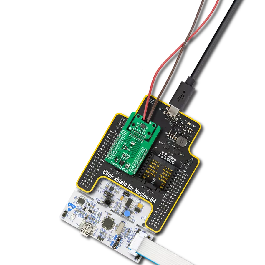
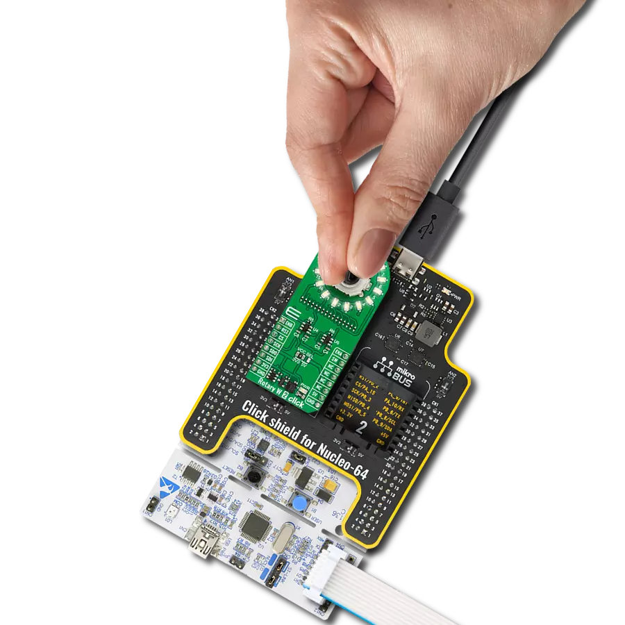
Click Shield for Nucleo-64 comes equipped with two proprietary mikroBUS™ sockets, allowing all the Click board™ devices to be interfaced with the STM32 Nucleo-64 board with no effort. This way, Mikroe allows its users to add any functionality from our ever-growing range of Click boards™, such as WiFi, GSM, GPS, Bluetooth, ZigBee, environmental sensors, LEDs, speech recognition, motor control, movement sensors, and many more. More than 1537 Click boards™, which can be stacked and integrated, are at your disposal. The STM32 Nucleo-64 boards are based on the microcontrollers in 64-pin packages, a 32-bit MCU with an ARM Cortex M4 processor operating at 84MHz, 512Kb Flash, and 96KB SRAM, divided into two regions where the top section represents the ST-Link/V2 debugger and programmer while the bottom section of the board is an actual development board. These boards are controlled and powered conveniently through a USB connection to program and efficiently debug the Nucleo-64 board out of the box, with an additional USB cable connected to the USB mini port on the board. Most of the STM32 microcontroller pins are brought to the IO pins on the left and right edge of the board, which are then connected to two existing mikroBUS™ sockets. This Click Shield also has several switches that perform functions such as selecting the logic levels of analog signals on mikroBUS™ sockets and selecting logic voltage levels of the mikroBUS™ sockets themselves. Besides, the user is offered the possibility of using any Click board™ with the help of existing bidirectional level-shifting voltage translators, regardless of whether the Click board™ operates at a 3.3V or 5V logic voltage level. Once you connect the STM32 Nucleo-64 board with our Click Shield for Nucleo-64, you can access hundreds of Click boards™, working with 3.3V or 5V logic voltage levels.

Used MCU Pins
mikroBUS™ mapper
Take a closer look
Click board™ Schematic
Step by step
Project assembly
Start by selecting your development board and Click board™. Begin with the Nucleo 64 with STM32F410RB MCU as your development board.


Software Support
Library Description
This library contains API for Rotary W 2 Click driver.
Key functions:
rotaryw2_set_led_pos- Rotary W 2 set LED position function.rotaryw2_set_led_data- Rotary W 2 set LED data function.rotaryw2_get_state_switch- Rotary W 2 get switch state function.
Open Source
Code example
The complete application code and a ready-to-use project are available through the NECTO Studio Package Manager for direct installation in the NECTO Studio. The application code can also be found on the MIKROE GitHub account.
/*!
 * @file main.c
 * @brief Rotary W 2 Click example
 *
 * # Description
 * This library contains the API for the Rotary W 2 Click driver
 * to control LEDs states and a rotary encoder position readings.
 *
 * The demo application is composed of two sections :
 *
 * ## Application Init
 * Initialization of SPI module and log UART.
 * After the driver init, the app executes a default configuration and turn off all LEDs.
 *
 * ## Application Task
 * This example demonstrates the use of the Rotary W 2 Click board™.
 * The demo example shows the functionality of a rotary encoder used to control LEDs.
 *
 * @author Nenad Filipovic
 *
 */

#include "board.h"
#include "log.h"
#include "rotaryw2.h"

#define ROTARYW2_ONE_LED          ROTARYW2_SET_LED_DATA_1
#define ROTARYW2_TWO_LED          ROTARYW2_SET_LED_DATA_1  | ROTARYW2_SET_LED_DATA_9
#define ROTARYW2_FOUR_LED         ROTARYW2_SET_LED_DATA_1  | ROTARYW2_SET_LED_DATA_5  | \
                                  ROTARYW2_SET_LED_DATA_9  | ROTARYW2_SET_LED_DATA_13
#define ROTARYW2_EIGHT_LED        ROTARYW2_SET_LED_DATA_1  | ROTARYW2_SET_LED_DATA_3  | \
                                  ROTARYW2_SET_LED_DATA_5  | ROTARYW2_SET_LED_DATA_7  | \
                                  ROTARYW2_SET_LED_DATA_9  | ROTARYW2_SET_LED_DATA_11 | \
                                  ROTARYW2_SET_LED_DATA_13 | ROTARYW2_SET_LED_DATA_15
#define ROTARYW2_EIGHT_LED_INV    ROTARYW2_SET_LED_DATA_2  | ROTARYW2_SET_LED_DATA_4  | \
                                  ROTARYW2_SET_LED_DATA_6  | ROTARYW2_SET_LED_DATA_8  | \
                                  ROTARYW2_SET_LED_DATA_10 | ROTARYW2_SET_LED_DATA_12 | \
                                  ROTARYW2_SET_LED_DATA_14 | ROTARYW2_SET_LED_DATA_16

static rotaryw2_t rotaryw2;
static log_t logger;

static uint8_t start_rot_status = 0;
static uint8_t led_demo_state = 0;
static uint8_t old_state = 0;
static uint8_t new_state = 1;
static uint8_t old_rot_state = 0;
static uint8_t new_rot_state = 1;
static uint16_t led_data = 1;

/**
 * @brief Rotary W 2 select LED demo data function.
 * @details This function selects one of the four LED demo data
 * based on the current state of the LED demo.
 * @return LED demo data:
 *         @li @c 0x0001 (ROTARYW2_ONE_LED)   - Turn ON LED[1],
 *         @li @c 0x0101 (ROTARYW2_TWO_LED)   - Turn ON LED[1,9],
 *         @li @c 0x0101 (ROTARYW2_FOUR_LED)  - Turn ON LED[1,5,9,13],
 *         @li @c 0x5555 (ROTARYW2_EIGHT_LED) - Turn ON LED[1,3,5,7,9,11,13,15].
 */
static uint16_t rotaryw2_sel_led_demo_data ( uint8_t led_demo_state );

/**
 * @brief Rotary W 2 switch detection function.
 * @details This function is used for the switch state detection.
 * @return Nothing.
 */
static void rotaryw2_switch_detection ( void );

/**
 * @brief Rotary W 2 encoder mechanism function.
 * @details This function is used to control the state of the LEDs
 * by detecting the rotation direction of the rotary encoder.
 * @return Nothing.
 */
static void rotaryw2_encoder_mechanism ( void );

void application_init ( void )
{
    log_cfg_t log_cfg;  /**< Logger config object. */
    rotaryw2_cfg_t rotaryw2_cfg;  /**< Click config object. */

    /**
     * Logger initialization.
     * Default baud rate: 115200
     * Default log level: LOG_LEVEL_DEBUG
     * @note If USB_UART_RX and USB_UART_TX
     * are defined as HAL_PIN_NC, you will
     * need to define them manually for log to work.
     * See @b LOG_MAP_USB_UART macro definition for detailed explanation.
     */
    LOG_MAP_USB_UART( log_cfg );
    log_init( &logger, &log_cfg );
    log_info( &logger, " Application Init " );

    // Click initialization.
    rotaryw2_cfg_setup( &rotaryw2_cfg );
    ROTARYW2_MAP_MIKROBUS( rotaryw2_cfg, MIKROBUS_1 );
    if ( SPI_MASTER_ERROR == rotaryw2_init( &rotaryw2, &rotaryw2_cfg ) )
    {
        log_error( &logger, " Communication init." );
        for ( ; ; );
    }

    if ( ROTARYW2_ERROR == rotaryw2_default_cfg ( &rotaryw2 ) )
    {
        log_error( &logger, " Default configuration." );
        for ( ; ; );
    }

    log_info( &logger, " Application Task " );
}

void application_task ( void )
{
    if ( ROTARYW2_OK == rotaryw2_set_led_data( &rotaryw2, led_data ) )
    {
        rotaryw2_switch_detection( );
        rotaryw2_encoder_mechanism( );
    }
}

int main ( void )
{
    /* Do not remove this line or clock might not be set correctly. */
    #ifdef PREINIT_SUPPORTED
    preinit();
    #endif

    application_init( );

    for ( ; ; )
    {
        application_task( );
    }

    return 0;
}

static uint16_t rotaryw2_sel_led_demo_data ( uint8_t led_demo_state )
{
    switch ( led_demo_state )
    {
        case 0:
        {
            return ROTARYW2_ONE_LED;
            break;
        }
        case 1:
        {
            return ROTARYW2_TWO_LED;
            break;
        }
        case 2:
        {
            return ROTARYW2_FOUR_LED;
            break;
        }
        case 3:
        {
            return ROTARYW2_EIGHT_LED;
            break;
        }
        default:
        {
            return ROTARYW2_ONE_LED;
            break;
        }
    }
}

static void rotaryw2_switch_detection ( void )
{
    if ( rotaryw2_get_state_switch( &rotaryw2 ) )
    {
        new_state = 1;
        if ( (  1 == new_state ) && ( 0 == old_state ) )
        {
            old_state = 1;
            led_demo_state = ( led_demo_state + 1 ) % 5;
            if ( 4 == led_demo_state )
            {
                for ( uint8_t n_cnt = 0; n_cnt < 10; n_cnt++ )
                {
                    rotaryw2_set_led_data( &rotaryw2, ROTARYW2_EIGHT_LED_INV );
                    Delay_ms ( 100 );
                    rotaryw2_set_led_data( &rotaryw2, ROTARYW2_EIGHT_LED );
                    Delay_ms ( 100 );
                }

                for ( uint8_t led_p = ROTARYW2_SET_LED_POS_1; led_p <= ROTARYW2_SET_LED_POS_16; led_p++ )
                {
                    rotaryw2_set_led_pos( &rotaryw2, led_p );
                    Delay_ms ( 100 );
                }

                led_demo_state = 0;
                led_data = rotaryw2_sel_led_demo_data( led_demo_state );
            }
            else
            {
                led_data = rotaryw2_sel_led_demo_data( led_demo_state );
            }
        }
    }
    else
    {
        old_state = 0;
    }
}

static void rotaryw2_encoder_mechanism ( void )
{
    if ( rotaryw2_get_state_ena( &rotaryw2 ) == rotaryw2_get_state_enb( &rotaryw2 ) )
    {
        old_rot_state = 0;
        start_rot_status = rotaryw2_get_state_ena( &rotaryw2 ) && rotaryw2_get_state_enb( &rotaryw2 );
    }
    else
    {
        new_rot_state = 1;
        if ( new_rot_state != old_rot_state )
        {
            old_rot_state = 1;
            if ( start_rot_status != rotaryw2_get_state_ena( &rotaryw2 ) )
            {
                led_data = ( led_data << 1 ) | ( led_data >> 15 );
            }
            else
            {
                led_data = ( led_data >> 1 ) | ( led_data << 15 );
            }
        }
    }
}

// ------------------------------------------------------------------------ END
Additional Support
Resources
Category:Rotary encoder