Bridge TTL/CMOS to RS232 using MAX3237E and STM32L073RZ
Where logic meets legacy: UART to RS232 made simple

Published Feb 26, 2024
Click board™
RS232 2 Click
Development board
Nucleo-64 with STM32L073RZ MCU
Compiler
NECTO Studio
MCU
STM32L073RZ
Unlock the full potential of serial communication with our UART-to-RS232 bridge, offering effortless signal conversion and data transfer capabilities
A
A
Hardware Overview
How does it work?
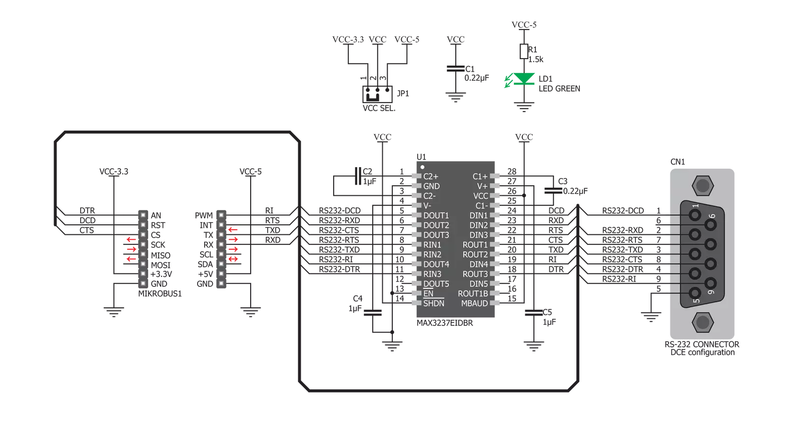
RS232 2 Click is based on the MAX3237E, a 3V to 5.5V multichannel RS232, 1 Mbit/s line driver/receiver from Texas Instruments. This device allows communication at 1 Mbit/s and allows 5V logic levels, even when working with 3.3V power supply. However, there is an onboard SMD jumper that allows selection of power supply voltage between 3.3V and 5V, if there is a requirement. The MAX3237E IC consists of five line drivers, three line receivers, and a dual charge pump circuit with ±15 kV pin to pin ESD protection for the serial port I/O pins. Those charge pumps along with the external capacitors, allow the device to run from a single 3V to 5.5V supply, providing the required RS232
voltage levels, which can go up to ±15 V as per standard. The MAX3237E IC generates an RS232 voltage in the range of ±13 V and accepts RS232 signal levels in the range of ±25 V. To provide the minimal functionality of the UART interface, at least three data lines have to be used: RX line, routed to the mikroBUS™ RX pin (on the click board side), TX line, routed to the mikroBUS™ TX pin (on the click board side), and the GND. Otherwise, this device supports the full stack of RS232 control lines, excluding the Data Set Ready line (DSR). Other relevant RS232 bus lines routed to the mikroBUS™ pins are: Data Terminal Ready (DTR) - routed to the AN pin, Data Carrier Detect
(DCD) - routed to the RST pin, Clear To Send (CTS) - routed to the CS pin, Ring Indicator (RI) - routed to the PWM pin, Request To Send (RTS) - routed to the INT pin. All these lines, are actually control lines and are used optionally by the RS232 device. RS232 2 click features the standardized DE-9 connector for easy connection to the RS232 device. By switching the VCC SEL jumper, it is possible to select the power supply voltage for the RS232 2 click. Although it can work with 5V, the device will accept UART signals of 5V even while working in 3.3V mode.


Features overview
Development board
Nucleo-64 with STM32L073RZ MCU offers a cost-effective and adaptable platform for developers to explore new ideas and prototype their designs. This board harnesses the versatility of the STM32 microcontroller, enabling users to select the optimal balance of performance and power consumption for their projects. It accommodates the STM32 microcontroller in the LQFP64 package and includes essential components such as a user LED, which doubles as an ARDUINO® signal, alongside user and reset push-buttons, and a 32.768kHz crystal oscillator for precise timing operations. Designed with expansion and flexibility in mind, the Nucleo-64 board features an ARDUINO® Uno V3 expansion connector and ST morpho extension pin
headers, granting complete access to the STM32's I/Os for comprehensive project integration. Power supply options are adaptable, supporting ST-LINK USB VBUS or external power sources, ensuring adaptability in various development environments. The board also has an on-board ST-LINK debugger/programmer with USB re-enumeration capability, simplifying the programming and debugging process. Moreover, the board is designed to simplify advanced development with its external SMPS for efficient Vcore logic supply, support for USB Device full speed or USB SNK/UFP full speed, and built-in cryptographic features, enhancing both the power efficiency and security of projects. Additional connectivity is
provided through dedicated connectors for external SMPS experimentation, a USB connector for the ST-LINK, and a MIPI® debug connector, expanding the possibilities for hardware interfacing and experimentation. Developers will find extensive support through comprehensive free software libraries and examples, courtesy of the STM32Cube MCU Package. This, combined with compatibility with a wide array of Integrated Development Environments (IDEs), including IAR Embedded Workbench®, MDK-ARM, and STM32CubeIDE, ensures a smooth and efficient development experience, allowing users to fully leverage the capabilities of the Nucleo-64 board in their projects.

Microcontroller Overview
MCU Card / MCU

Architecture
ARM Cortex-M0
MCU Memory (KB)
192
Silicon Vendor
STMicroelectronics
Pin count
64
RAM (Bytes)
20480
You complete me!
Accessories
Click Shield for Nucleo-64 comes equipped with two proprietary mikroBUS™ sockets, allowing all the Click board™ devices to be interfaced with the STM32 Nucleo-64 board with no effort. This way, Mikroe allows its users to add any functionality from our ever-growing range of Click boards™, such as WiFi, GSM, GPS, Bluetooth, ZigBee, environmental sensors, LEDs, speech recognition, motor control, movement sensors, and many more. More than 1537 Click boards™, which can be stacked and integrated, are at your disposal. The STM32 Nucleo-64 boards are based on the microcontrollers in 64-pin packages, a 32-bit MCU with an ARM Cortex M4 processor operating at 84MHz, 512Kb Flash, and 96KB SRAM, divided into two regions where the top section represents the ST-Link/V2 debugger and programmer while the bottom section of the board is an actual development board. These boards are controlled and powered conveniently through a USB connection to program and efficiently debug the Nucleo-64 board out of the box, with an additional USB cable connected to the USB mini port on the board. Most of the STM32 microcontroller pins are brought to the IO pins on the left and right edge of the board, which are then connected to two existing mikroBUS™ sockets. This Click Shield also has several switches that perform functions such as selecting the logic levels of analog signals on mikroBUS™ sockets and selecting logic voltage levels of the mikroBUS™ sockets themselves. Besides, the user is offered the possibility of using any Click board™ with the help of existing bidirectional level-shifting voltage translators, regardless of whether the Click board™ operates at a 3.3V or 5V logic voltage level. Once you connect the STM32 Nucleo-64 board with our Click Shield for Nucleo-64, you can access hundreds of Click boards™, working with 3.3V or 5V logic voltage levels.

DB9 Cable Female-to-Female (2m) cable is essential for establishing dependable serial data connections between devices. With its DB9 female connectors on both ends, this cable enables a seamless link between various equipment, such as computers, routers, switches, and other serial devices. Measuring 2 meters in length, it offers flexibility in arranging your setup without compromising data transmission quality. Crafted with precision, this cable ensures consistent and reliable data exchange, making it suitable for industrial applications, office environments, and home setups. Whether configuring networking equipment, accessing console ports, or utilizing serial peripherals, this cable's durable construction and robust connectors guarantee a stable connection. Simplify your data communication needs with the 2m DB9 female-to-female cable, an efficient solution designed to meet your serial connectivity requirements easily and efficiently.

Used MCU Pins
mikroBUS™ mapper
Take a closer look
Schematic
Step by step
Project assembly
Start by selecting your development board and Click board™. Begin with the Nucleo-64 with STM32L073RZ MCU as your development board.


Track your results in real time
Application Output
After loading the code example, pressing the "DEBUG" button builds and programs it on the selected setup.

After programming is completed, a header with buttons for various actions available in the IDE appears. By clicking the green "PLAY "button, we start reading the results achieved with Click board™.

Upon completion of programming, the Application Output tab is automatically opened, where the achieved result can be read. In case of an inability to perform the Debug function, check if a proper connection between the MCU used by the setup and the CODEGRIP programmer has been established. A detailed explanation of the CODEGRIP-board connection can be found in the CODEGRIP User Manual. Please find it in the RESOURCES section.

Software Support
Library Description
This library contains API for RS232 2 Click driver.
Key functions:
rs2322_set_cts- This function sets CTS pin staters2322_get_dtr- This function get DTR pin staters2322_send_command- Function for send command
Open Source
Code example
This example can be found in NECTO Studio. Feel free to download the code, or you can copy the code below.
/*!
 * \file
 * \brief Rs2322 Click example
 *
 * # Description
 * This example reads and processes data from RS232 2 clicks.
 *
 * The demo application is composed of two sections :
 *
 * ## Application Init
 * Initializes driver.
 *
 * ## Application Task
 * Reads the received data.
 *
 * ## Additional Function
 * - rs2322_process ( ) - The general process of collecting presponce
 *                                   that sends a module.
 *
 * \author MikroE Team
 *
 */
// ------------------------------------------------------------------- INCLUDES

#include "board.h"
#include "log.h"
#include "rs2322.h"
#include "string.h"

#define PROCESS_COUNTER 10
#define PROCESS_RX_BUFFER_SIZE 500
#define PROCESS_PARSER_BUFFER_SIZE 500

#define TEXT_TO_SEND  "MikroE\r\n"

// ------------------------------------------------------------------ VARIABLES

#define DEMO_APP_RECEIVER
//#define DEMO_APP_TRANSMITER

static rs2322_t rs2322;
static log_t logger;

static char current_rsp_buf[ PROCESS_PARSER_BUFFER_SIZE ];
static uint8_t send_data_cnt = 0;
// ------------------------------------------------------- ADDITIONAL FUNCTIONS

static void rs2322_process ( void )
{
    int16_t rsp_size;
    uint16_t rsp_cnt = 0;

    char uart_rx_buffer[ PROCESS_RX_BUFFER_SIZE ] = { 0 };
    uint8_t check_buf_cnt;
    uint8_t process_cnt = PROCESS_COUNTER;

    // Clear parser buffer
    memset( current_rsp_buf, 0 , PROCESS_PARSER_BUFFER_SIZE );

    while( process_cnt != 0 )
    {
        rsp_size = rs2322_generic_read( &rs2322, &uart_rx_buffer, PROCESS_RX_BUFFER_SIZE );

        if ( rsp_size > 0 )
        {
            // Validation of the received data
            for ( check_buf_cnt = 0; check_buf_cnt < rsp_size; check_buf_cnt++ )
            {
                if ( uart_rx_buffer[ check_buf_cnt ] == 0 )
                {
                    uart_rx_buffer[ check_buf_cnt ] = 13;
                }
            }

            log_printf( &logger, "%s\r\n", uart_rx_buffer );

            // Storages data in parser buffer
            rsp_cnt += rsp_size;
            if ( rsp_cnt < PROCESS_PARSER_BUFFER_SIZE )
            {
                strncat( current_rsp_buf, uart_rx_buffer, rsp_size );
            }

            // Clear RX buffer
            memset( uart_rx_buffer, 0, PROCESS_RX_BUFFER_SIZE );
        }
        else
        {
            process_cnt--;

            // Process delay
            Delay_ms( 100 );
        }
    }
    log_printf( &logger, "%s\r\n", current_rsp_buf );
}

// ------------------------------------------------------ APPLICATION FUNCTIONS

void application_init ( void )
{
    log_cfg_t log_cfg;
    rs2322_cfg_t cfg;

    /**
     * Logger initialization.
     * Default baud rate: 115200
     * Default log level: LOG_LEVEL_DEBUG
     * @note If USB_UART_RX and USB_UART_TX
     * are defined as HAL_PIN_NC, you will
     * need to define them manually for log to work.
     * See @b LOG_MAP_USB_UART macro definition for detailed explanation.
     */
    LOG_MAP_USB_UART( log_cfg );
    log_init( &logger, &log_cfg );
    log_info( &logger, "---- Application Init ----" );

    //  Click initialization.

    rs2322_cfg_setup( &cfg );
    RS2322_MAP_MIKROBUS( cfg, MIKROBUS_1 );
    rs2322_init( &rs2322, &cfg );
}

void application_task ( void )
{
#ifdef DEMO_APP_RECEIVER
    rs2322_process( );
#endif

#ifdef DEMO_APP_TRANSMITER
    rs2322_process( );

    if ( send_data_cnt == 5 )
    {
        rs2322_send_command( &rs2322, TEXT_TO_SEND );
        send_data_cnt = 0;
    }
    else
    {
        send_data_cnt++;
    }
#endif
}

void main ( void )
{
    application_init( );

    for ( ; ; )
    {
        application_task( );
    }
}

// ------------------------------------------------------------------------ END


