Unlock the secrets of time with DS1343 combined with STM32F091RC
RTC: Time's trusted guardians in the digital age

Published Feb 26, 2024
Click board™
RTC 12 Click
Dev. board
Nucleo-64 with STM32F091RC MCU
Compiler
NECTO Studio
MCU
STM32F091RC
Optimize your engineering projects with efficient real-time clock, delivering reliable and accurate timekeeping for critical operations
A
A
Hardware Overview
How does it work?
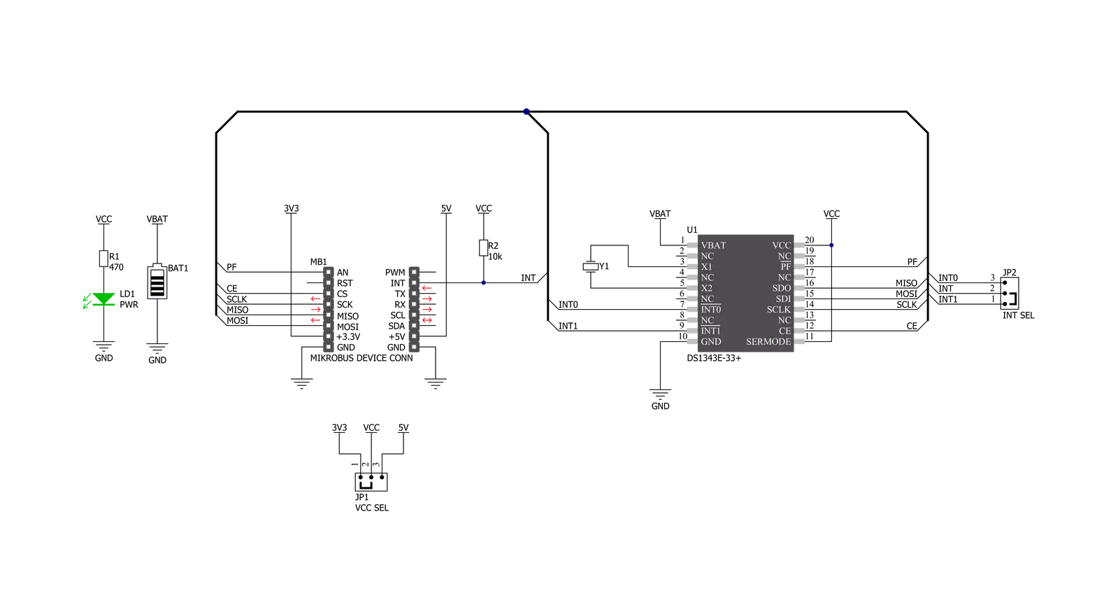
RTC 12 Click is based on the DS1343, a low-current RTC that consumes an extremely low timekeeping current, permitting longer life from a backup supply source from Analog Devices. The devices provide a full binary-coded decimal clock calendar accessed by a simple serial interface. The clock/calendar provides information on seconds, minutes, hours, days, dates, months, and years. The month's end date is automatically adjusted for months with fewer than 31 days, including corrections for the leap year through 2099. The clock operates in either a 24-hour or 12-hour format with an AM/PM indicator. As performed on this Click board™, the most common configuration is a battery-backed-up RTC, which maintains time and may hold data in 96 bytes of NV RAM provided for data storage. In addition to
the DS1343, the RTC 12 Click is equipped with a button cell battery holder compatible with the 3000TR battery holder, suitable for 12mm Coin Cell batteries. Furthermore, it has a built-in temperature-compensated power-sense circuit that detects power failures and automatically switches to the backup supply, thus allowing for uninterrupted operation. The DS1343 communicates with MCU using the standard SPI serial interface that supports modes 1 and 3 with a maximum frequency of 4 MHz. It also provides two programmable time-of-day alarms. Each alarm can generate an interrupt on a programmable combination of seconds, minutes, hours, and days, available on the INT pin of the mikroBUS™ socket. The interrupt selection can be made by positioning the SMD jumper labeled INT SEL to an
appropriate position. Both interrupt outputs operate when the device is powered by mikroBUS™ power rails or backup supply voltage. In addition to the features mentioned above, the user can use another indicator routed to the AN pin of the mikroBUS™ socket labeled as PF to indicate a loss of a primary power supply, VCC, from mikroBUS™ power rails. This Click board™ can operate with either 3.3V or 5V logic voltage levels selected via the VCC SEL jumper. This way, both 3.3V and 5V capable MCUs can use the communication lines properly. Also, this Click board™ comes equipped with a library containing easy-to-use functions and an example code that can be used as a reference for further development.


Features overview
Development board
Nucleo-64 with STM32F091RC MCU offers a cost-effective and adaptable platform for developers to explore new ideas and prototype their designs. This board harnesses the versatility of the STM32 microcontroller, enabling users to select the optimal balance of performance and power consumption for their projects. It accommodates the STM32 microcontroller in the LQFP64 package and includes essential components such as a user LED, which doubles as an ARDUINO® signal, alongside user and reset push-buttons, and a 32.768kHz crystal oscillator for precise timing operations. Designed with expansion and flexibility in mind, the Nucleo-64 board features an ARDUINO® Uno V3 expansion connector and ST morpho extension pin
headers, granting complete access to the STM32's I/Os for comprehensive project integration. Power supply options are adaptable, supporting ST-LINK USB VBUS or external power sources, ensuring adaptability in various development environments. The board also has an on-board ST-LINK debugger/programmer with USB re-enumeration capability, simplifying the programming and debugging process. Moreover, the board is designed to simplify advanced development with its external SMPS for efficient Vcore logic supply, support for USB Device full speed or USB SNK/UFP full speed, and built-in cryptographic features, enhancing both the power efficiency and security of projects. Additional connectivity is
provided through dedicated connectors for external SMPS experimentation, a USB connector for the ST-LINK, and a MIPI® debug connector, expanding the possibilities for hardware interfacing and experimentation. Developers will find extensive support through comprehensive free software libraries and examples, courtesy of the STM32Cube MCU Package. This, combined with compatibility with a wide array of Integrated Development Environments (IDEs), including IAR Embedded Workbench®, MDK-ARM, and STM32CubeIDE, ensures a smooth and efficient development experience, allowing users to fully leverage the capabilities of the Nucleo-64 board in their projects.

Microcontroller Overview
MCU Card / MCU

Architecture
ARM Cortex-M0
MCU Memory (KB)
256
Silicon Vendor
STMicroelectronics
Pin count
64
RAM (Bytes)
32768
You complete me!
Accessories
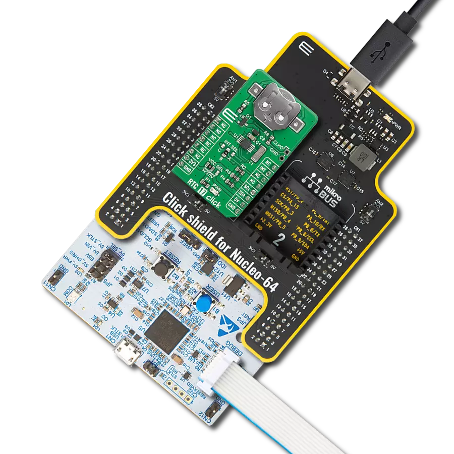
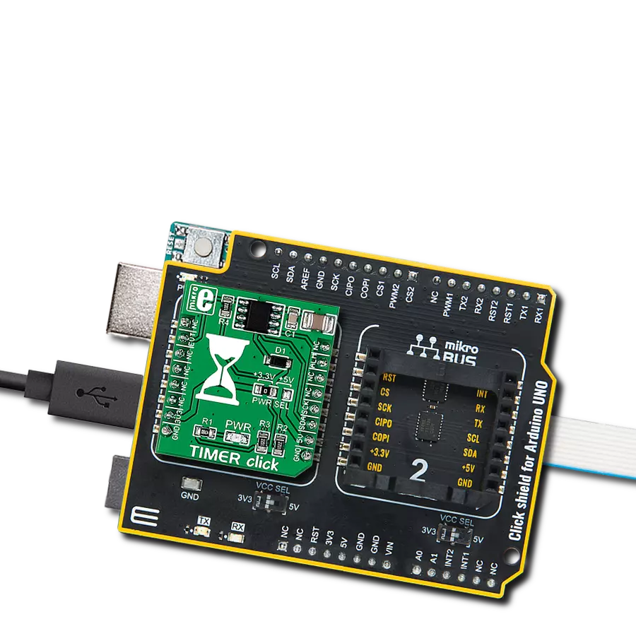
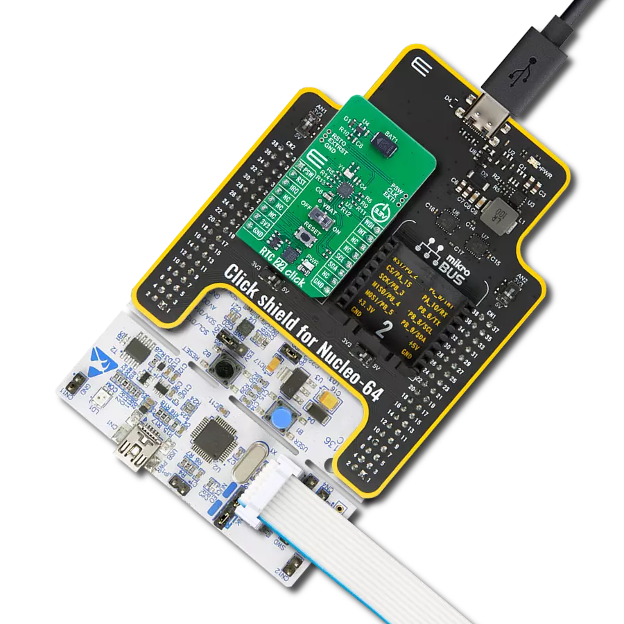
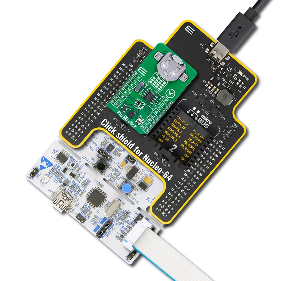
Click Shield for Nucleo-64 comes equipped with two proprietary mikroBUS™ sockets, allowing all the Click board™ devices to be interfaced with the STM32 Nucleo-64 board with no effort. This way, Mikroe allows its users to add any functionality from our ever-growing range of Click boards™, such as WiFi, GSM, GPS, Bluetooth, ZigBee, environmental sensors, LEDs, speech recognition, motor control, movement sensors, and many more. More than 1537 Click boards™, which can be stacked and integrated, are at your disposal. The STM32 Nucleo-64 boards are based on the microcontrollers in 64-pin packages, a 32-bit MCU with an ARM Cortex M4 processor operating at 84MHz, 512Kb Flash, and 96KB SRAM, divided into two regions where the top section represents the ST-Link/V2 debugger and programmer while the bottom section of the board is an actual development board. These boards are controlled and powered conveniently through a USB connection to program and efficiently debug the Nucleo-64 board out of the box, with an additional USB cable connected to the USB mini port on the board. Most of the STM32 microcontroller pins are brought to the IO pins on the left and right edge of the board, which are then connected to two existing mikroBUS™ sockets. This Click Shield also has several switches that perform functions such as selecting the logic levels of analog signals on mikroBUS™ sockets and selecting logic voltage levels of the mikroBUS™ sockets themselves. Besides, the user is offered the possibility of using any Click board™ with the help of existing bidirectional level-shifting voltage translators, regardless of whether the Click board™ operates at a 3.3V or 5V logic voltage level. Once you connect the STM32 Nucleo-64 board with our Click Shield for Nucleo-64, you can access hundreds of Click boards™, working with 3.3V or 5V logic voltage levels.

Used MCU Pins
mikroBUS™ mapper
Take a closer look
Click board™ Schematic
Step by step
Project assembly
Start by selecting your development board and Click board™. Begin with the Nucleo-64 with STM32F091RC MCU as your development board.


Track your results in real time
Application Output
1. Application Output - In Debug mode, the 'Application Output' window enables real-time data monitoring, offering direct insight into execution results. Ensure proper data display by configuring the environment correctly using the provided tutorial.

2. UART Terminal - Use the UART Terminal to monitor data transmission via a USB to UART converter, allowing direct communication between the Click board™ and your development system. Configure the baud rate and other serial settings according to your project's requirements to ensure proper functionality. For step-by-step setup instructions, refer to the provided tutorial.

3. Plot Output - The Plot feature offers a powerful way to visualize real-time sensor data, enabling trend analysis, debugging, and comparison of multiple data points. To set it up correctly, follow the provided tutorial, which includes a step-by-step example of using the Plot feature to display Click board™ readings. To use the Plot feature in your code, use the function: plot(*insert_graph_name*, variable_name);. This is a general format, and it is up to the user to replace 'insert_graph_name' with the actual graph name and 'variable_name' with the parameter to be displayed.

Software Support
Library Description
This library contains API for RTC 12 Click driver.
Key functions:
rtc12_set_time- RTC 12 set time functionrtc12_get_time- RTC 12 get time functionrtc12_get_date- RTC 12 get date function
Open Source
Code example
The complete application code and a ready-to-use project are available through the NECTO Studio Package Manager for direct installation in the NECTO Studio. The application code can also be found on the MIKROE GitHub account.
/*!
 * @file main.c
 * @brief Rtc12 Click example
 *
 * # Description
 * This is an example that demonstrates the use of the RTC 12 Click board™.
 *
 *
 * The demo application is composed of two sections :
 *
 * ## Application Init
 * Initialization of SPI module, log UART and additional pins.
 * After driver initialization and default settings,
 * the app set the time to 23:59:50 and set the date to 27.05.'21.
 *
 * ## Application Task
 * This is an example that shows the use of a RTC 12 Click board™.
 * In this example, we read and display the current time and date,
 * which we also previously set.
 * Results are being sent to the Usart Terminal where you can track their changes.
 * All data logs write on USB changes every 1 sec.
 *
 *
 * @author Nenad Filipovic
 *
 */

#include "board.h"
#include "log.h"
#include "rtc12.h"

static rtc12_t rtc12;
static log_t logger;

static uint8_t new_sec = 255;
static rtc12_time_t time;
static rtc12_date_t date;


void application_init ( void ) {
    log_cfg_t log_cfg;      /**< Logger config object. */
    rtc12_cfg_t rtc12_cfg;   /**< Click config object. */

    /**
     * Logger initialization.
     * Default baud rate: 115200
     * Default log level: LOG_LEVEL_DEBUG
     * @note If USB_UART_RX and USB_UART_TX
     * are defined as HAL_PIN_NC, you will
     * need to define them manually for log to work.
     * See @b LOG_MAP_USB_UART macro definition for detailed explanation.
     */
    LOG_MAP_USB_UART( log_cfg );
    log_init( &logger, &log_cfg );
    log_info( &logger, " Application Init " );

    // Click initialization.

    rtc12_cfg_setup( &rtc12_cfg );
    RTC12_MAP_MIKROBUS( rtc12_cfg, MIKROBUS_1 );
    err_t init_flag  = rtc12_init( &rtc12, &rtc12_cfg );
    if ( init_flag == SPI_MASTER_ERROR ) {
        log_error( &logger, " Application Init Error. " );
        log_info( &logger, " Please, run program again... " );

        for ( ; ; );
    }

    rtc12_default_cfg ( &rtc12 );
    log_info( &logger, " Application Task " );
    Delay_ms ( 100 );

    date.day_of_week = 4;
    date.day = 27;
    date.month = 5;
    date.year = 21;
    rtc12_set_date( &rtc12, date );
    Delay_ms ( 100 );

    time.hours = 23;
    time.min = 59;
    time.sec = 50;
    rtc12_set_time( &rtc12, time );
    Delay_ms ( 100 );
}

void application_task ( void ) {
    rtc12_get_time( &rtc12, &time );
    Delay_ms ( 1 );
    rtc12_get_date( &rtc12, &date );
    Delay_ms ( 1 );

    if ( time.sec != new_sec ) {
        log_printf( &logger, "  Date      : %.2d-%.2d-%.2d\r\n", ( uint16_t ) date.day, ( uint16_t ) date.month, ( uint16_t ) date.year );
        log_printf( &logger, "  Time      : %.2d:%.2d:%.2d\r\n", ( uint16_t ) time.hours, ( uint16_t ) time.min, ( uint16_t ) time.sec );
        log_printf( &logger, "- - - - - - - - - - - -\r\n" );
        new_sec = time.sec;
        Delay_ms ( 1 );
     }
}

int main ( void )
{
    /* Do not remove this line or clock might not be set correctly. */
    #ifdef PREINIT_SUPPORTED
    preinit();
    #endif

    application_init( );

    for ( ; ; )
    {
        application_task( );
    }

    return 0;
}

// ------------------------------------------------------------------------ END
Additional Support
Resources
Category:RTC