Elevate your pressure sensing expectations with MS5849-30BA and ATmega1284
Measure beyond limits: Our chlorine-resistant absolute pressure sensor
Published Jul 09, 2024
Click board™
Pressure 23 Click
Dev. board
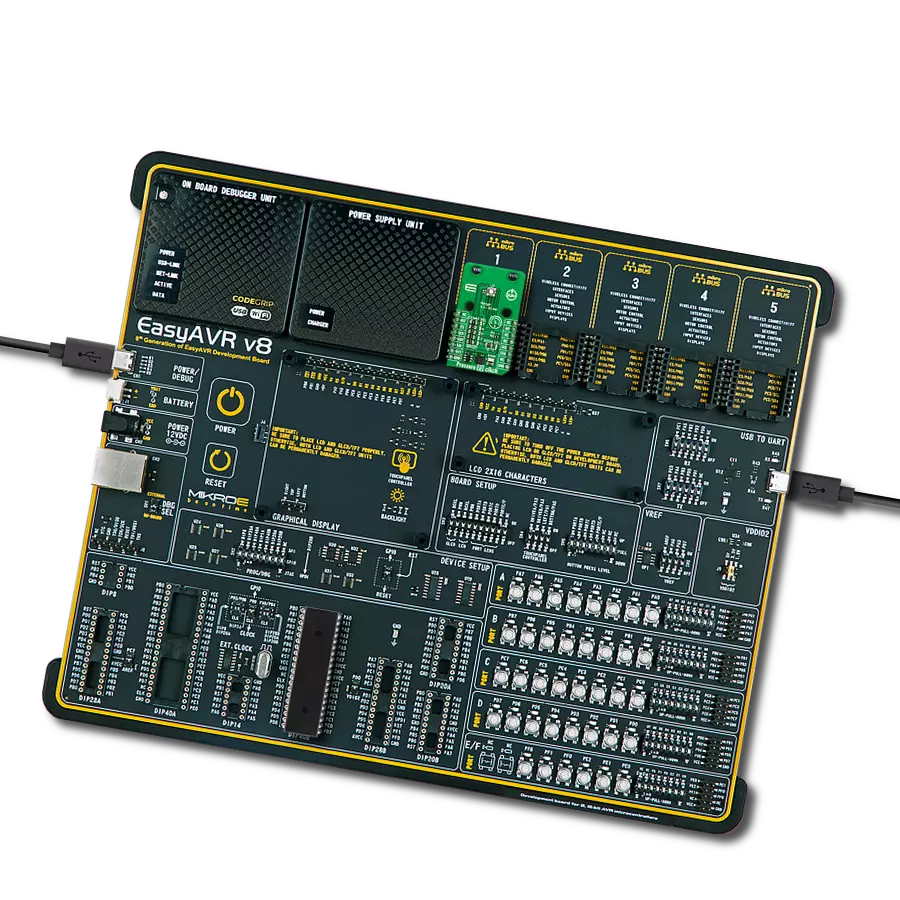
EasyAVR v8
Compiler
NECTO Studio
MCU
ATmega1284
Our absolute pressure sensor is not just resistant; it thrives in chlorine-rich environments, offering a solution that endures, measures, and repeats with unwavering precision in the face of challenging conditions.
A
A
Hardware Overview
How does it work?
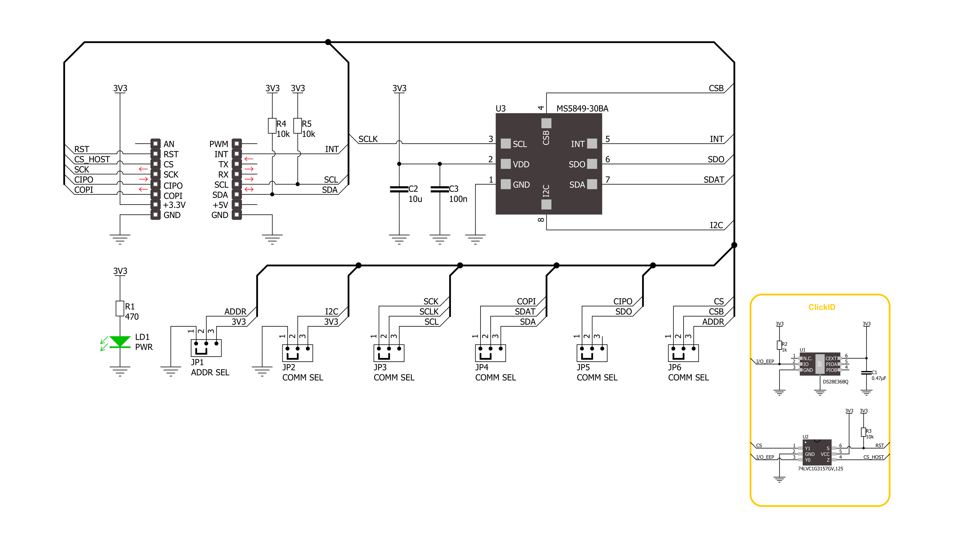
Pressure 23 Click is based on the MS5849-30BA, an ultra-compact chlorine-resistant absolute pressure sensor from TE Connectivity. It provides precise digital 24-bit pressure and temperature values and different operation modes, allowing users to optimize conversion speed and current consumption. The sensor features built-in automatic conversion, signaling state by interrupt, a programmable filter, and more. The sensor delivers a decent pressure sensing accuracy, which depends on the pressure measuring range. On lower pressures, it is as low as ±50mbar. In addition to pressure, this sensor can measure the temperature, which is needed for temperature compensation in a range of -20 up to 85°C with a temperature sensing accuracy of ±2°C. The MS5849-30BA includes a high linearity pressure sensor and an ultra-low power delta-sigma ADC
with internal factory-calibrated coefficients. The sensor consists of a piezo-resistive sensor and a sensor interface integrated circuit. It converts the sensor's uncompensated analog output value voltage to a 24-bit digital value. The sensor is individually factory calibrated, where, as a result, ten coefficients necessary to compensate for process variations and temperature variations are calculated and stored in the 256-bit NVRAM of the sensor. The sensor and the sealing gel on it shouldn't be touched or damaged in any way. In applications such as outdoor watches, the electronics must be protected against direct water or humidity. For such applications, the MS5849-30BA provides the possibility to seal with an O-ring. Pressure 23 Click can communicate with the host MCU using the 4-Wire SPI serial and I2C interfaces. The SPI interface supports clock
frequencies up to 20MHz, while the I2C clock supports up to 3.4MHz. The desired communication interface can be chosen over the 5 COMM SEL jumpers, where the SPI is set by default. If your goal is the I2C, you can choose the I2C address over the ADDR SEL jumper (0 set by default). The interrupt on the INT pin will be raised for different conditions, such as pressure and temperature thresholds, finished ADC conversion, and more. This Click board™ can be operated only with a 3.3V logic voltage level. The board must perform appropriate logic voltage level conversion before using MCUs with different logic levels. Also, it comes equipped with a library containing functions and an example code that can be used as a reference for further development.

Features overview
Development board
EasyAVR v8 is a development board designed to rapidly develop embedded applications based on 8-bit AVR microcontrollers (MCUs). Redesigned from the ground up, EasyAVR v8 offers a familiar set of standard features, as well as some new and unique features standard for the 8th generation of development boards: programming and debugging over the WiFi network, connectivity provided by USB-C connectors, support for a wide range of different MCUs, and more. The development board is designed so that the developer has everything that might be needed for the application development, following the Swiss Army knife concept: a highly advanced programmer/debugger module, a reliable power supply module, and a USB-UART connectivity option. EasyAVR v8 board offers several different DIP sockets, covering a wide range of 8-bit AVR MCUs, from the smallest
AVR MCU devices with only eight pins, all the way up to 40-pin "giants". The development board supports the well-established mikroBUS™ connectivity standard, offering five mikroBUS™ sockets, allowing access to a huge base of Click boards™. EasyAVR v8 offers two display options, allowing even the basic 8-bit AVR MCU devices to utilize them and display graphical or textual content. One of them is the 1x20 graphical display connector, compatible with the familiar Graphical Liquid Crystal Display (GLCD) based on the KS108 (or compatible) display driver, and EasyTFT board that contains TFT Color Display MI0283QT-9A, which is driven by ILI9341 display controller, capable of showing advanced graphical content. The other option is the 2x16 character LCD module, a four-bit display module with an embedded character-based display controller. It
requires minimal processing power from the host MCU for its operation. There is a wide range of useful interactive options at the disposal: high-quality buttons with selectable press levels, LEDs, pull-up/pulldown DIP switches, and more. All these features are packed on a single development board, which uses innovative manufacturing technologies, delivering a fluid and immersive working experience. The EasyAVR v8 development board is also integral to the MIKROE rapid development ecosystem. Natively supported by the MIKROE Software toolchain, backed up by hundreds of different Click board™ designs with their number growing daily, it covers many different prototyping and development aspects, thus saving precious development time.

Microcontroller Overview
MCU Card / MCU

Architecture
AVR
MCU Memory (KB)
128
Silicon Vendor
Microchip
Pin count
40
RAM (Bytes)
16384
Used MCU Pins
mikroBUS™ mapper
Take a closer look
Click board™ Schematic
Step by step
Project assembly

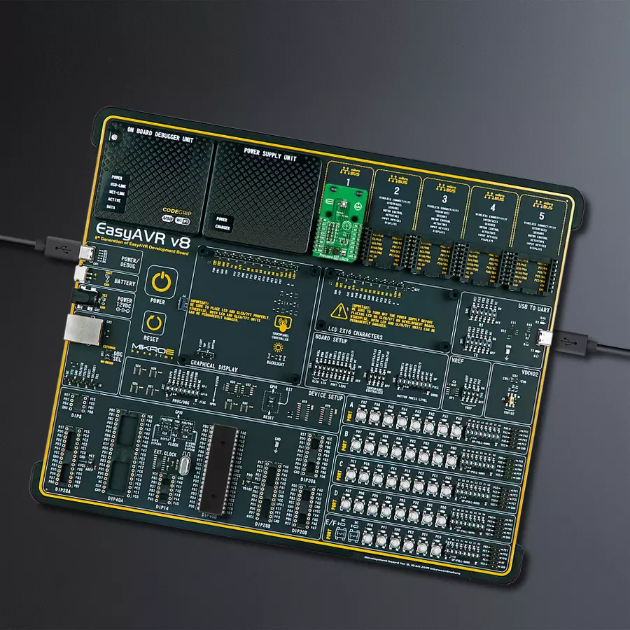
Start by selecting your development board and Click board™. Begin with the EasyAVR v8 as your development board.


Track your results in real time
Application Output
1. Application Output - In Debug mode, the 'Application Output' window enables real-time data monitoring, offering direct insight into execution results. Ensure proper data display by configuring the environment correctly using the provided tutorial.

2. UART Terminal - Use the UART Terminal to monitor data transmission via a USB to UART converter, allowing direct communication between the Click board™ and your development system. Configure the baud rate and other serial settings according to your project's requirements to ensure proper functionality. For step-by-step setup instructions, refer to the provided tutorial.

3. Plot Output - The Plot feature offers a powerful way to visualize real-time sensor data, enabling trend analysis, debugging, and comparison of multiple data points. To set it up correctly, follow the provided tutorial, which includes a step-by-step example of using the Plot feature to display Click board™ readings. To use the Plot feature in your code, use the function: plot(*insert_graph_name*, variable_name);. This is a general format, and it is up to the user to replace 'insert_graph_name' with the actual graph name and 'variable_name' with the parameter to be displayed.

Software Support
Library Description
This library contains API for Pressure 23 Click - 30BA driver.
Key functions:
pressure2330ba_get_measurement_data- Pressure 23 gets the measurement data function.pressure2330ba_get_calibration_data- Pressure 23 gets the calibration data function.pressure2330ba_read_adc- Pressure 23 ADC data reading function.
Open Source
Code example
The complete application code and a ready-to-use project are available through the NECTO Studio Package Manager for direct installation in the NECTO Studio. The application code can also be found on the MIKROE GitHub account.
/*!
 * @file main.c
 * @brief Pressure 23 30BA Click example
 *
 * # Description
 * This example demonstrates the use of Pressure 23 30BA Click board by reading and displaying
 * the pressure and temperature measurements.
 *
 * The demo application is composed of two sections :
 *
 * ## Application Init
 * The initialization of I2C or SPI module and log UART.
 * After driver initialization, the app sets the default configuration.
 *
 * ## Application Task
 * The demo application reads and displays the Pressure [mBar]
 * and Temperature [degree Celsius] data.
 * Results are being sent to the UART Terminal, where you can track their changes.
 *
 * @author Nenad Filipovic
 *
 */

#include "board.h"
#include "log.h"
#include "pressure2330ba.h"

static pressure2330ba_t pressure2330ba;
static log_t logger;

void application_init ( void )
{
    log_cfg_t log_cfg;  /**< Logger config object. */
    pressure2330ba_cfg_t pressure2330ba_cfg;  /**< Click config object. */

    /**
     * Logger initialization.
     * Default baud rate: 115200
     * Default log level: LOG_LEVEL_DEBUG
     * @note If USB_UART_RX and USB_UART_TX
     * are defined as HAL_PIN_NC, you will
     * need to define them manually for log to work.
     * See @b LOG_MAP_USB_UART macro definition for detailed explanation.
     */
    LOG_MAP_USB_UART( log_cfg );
    log_init( &logger, &log_cfg );
    log_info( &logger, " Application Init " );

    // Click initialization.
    pressure2330ba_cfg_setup( &pressure2330ba_cfg );
    PRESSURE2330BA_MAP_MIKROBUS( pressure2330ba_cfg, MIKROBUS_1 );
    err_t init_flag = pressure2330ba_init( &pressure2330ba, &pressure2330ba_cfg );
    if ( ( I2C_MASTER_ERROR == init_flag ) || ( SPI_MASTER_ERROR == init_flag ) )
    {
        log_error( &logger, " Communication init." );
        for ( ; ; );
    }

    if ( PRESSURE2330BA_ERROR == pressure2330ba_default_cfg ( &pressure2330ba ) )
    {
        log_error( &logger, " Default configuration." );
        for ( ; ; );
    }

    log_info( &logger, " Application Task " );
    log_printf( &logger, " _______________________ \r\n" );
    Delay_ms ( 100 );
}

void application_task ( void )
{
    static float temperature, pressure;
    if ( PRESSURE2330BA_OK == pressure2330ba_get_measurement_data( &pressure2330ba, &pressure, &temperature ) )
    {
        log_printf( &logger, " Pressure    : %.2f mBar \r\n", pressure );
        log_printf( &logger, " Temperature : %.2f degC \r\n", temperature );
        log_printf( &logger, " _______________________ \r\n" );
        Delay_ms ( 1000 );
    }
}

int main ( void )
{
    /* Do not remove this line or clock might not be set correctly. */
    #ifdef PREINIT_SUPPORTED
    preinit();
    #endif

    application_init( );

    for ( ; ; )
    {
        application_task( );
    }

    return 0;
}

// ------------------------------------------------------------------------ END


