Unleash the waveform symphony using AD9833 and ATmega32A
Sine/triangle/square waveform generator

Published Jul 11, 2024
Click board™
Waveform Click
Dev. board
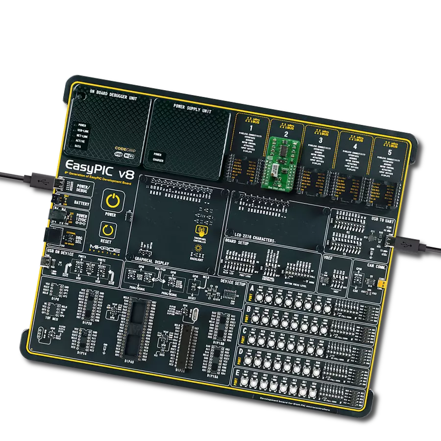
EasyAVR v8
Compiler
NECTO Studio
MCU
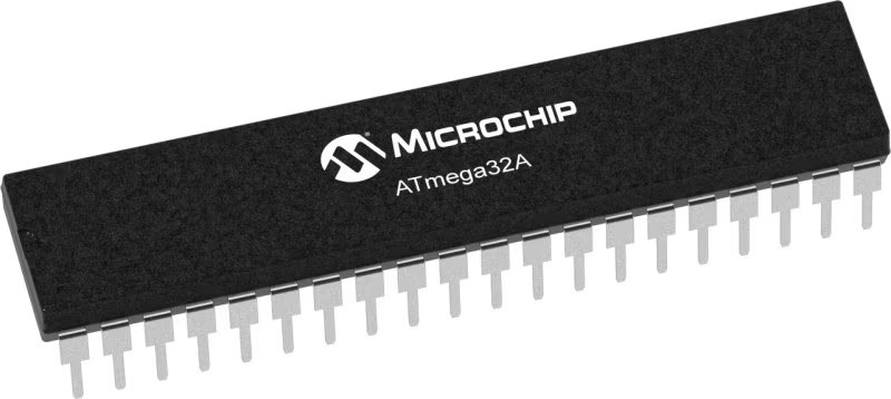
ATmega32A
Explore this comprehensive waveform generator and add seamless signal generation to your solution
A
A
Hardware Overview
How does it work?
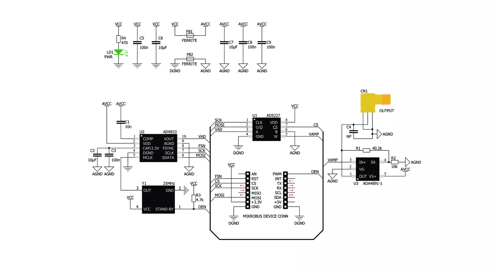
Waveform Click is based on the AD9833, a low-power, programmable waveform generator from Analog Devices. This company is well-established in the high-quality Digital Signal Processing (DSP) solutions market. The AD9833 IC is based on Direct Digital Synthesis (DDS), producing a waveform with a programmable frequency and selectable wave shape at its output. The AD9833 and the AD5227, a digital potentiometer IC from the same company, are controlled over the SPI interface, allowing both the frequency and amplitude to be changed very quickly without additional latency. DDS produces an analog waveform by exploiting the fact that the signal's phase is changed linearly. For simple periodic functions such as the sine function, the phase changes linearly between 0 and 2π. This allows building the Numerically Controlled Oscillator (NCO) block, which outputs a numerical value that linearly changes over time, between 0 and 228 – 1 (since the AD9833 IC has a 28-bit phase accumulator). The continuously changing output of the NCO block is used as the index for the Lookup Table (LUT), which contains amplitudes of the output waveform. The faster the NCO output changes, the higher the output signal frequency,
which is a basis for DDS. The main advantage over other types of synthesis (PLL, for example) is its simplistic approach. The frequency can be changed in small steps (depending on the clock generator), while the maximum frequency can easily reach GHz. Besides the NCO and the LUT, the AD9833 contains other blocks necessary to produce the waveform at the output. It also features a 10-bit DAC, which translates the digital value into an analog voltage at the output. Since the ADC is only 10 bits wide, the LUT does not need to have too many elements. The resolution of the ADC is the bottleneck, so a slightly higher resolution is required for the LUT data. This further reduces the complexity and costs. The AD9833 can completely avoid using the LUT, producing a square wave (by using only the MSB of the DAC), with a frequency that can be further multiplied by 2, and a triangle wave (by redirecting the NCO directly to DAC instead using it for sweeping through the LUT). The operating modes of the AD9833 can be set up by using the config-register over the SPI interface. For more detailed information about the AD9833 IC, please refer to the datasheet of the AD9833. However, the mikroSDK compatible library contains functions
that simplify work with the AD9833 IC. The output of the AD9833 is routed to the AD5227 digital potentiometer, which is used to set the amplitude of the output signal. This potentiometer is used to scale down the amplitude between 0V and 3.3V. It is controlled over the SPI interface. The potentiometer is used since the AD9833 IC does not provide means to regulate the amplitude of the signal at the output. Waveform click uses the clock generator 25MHz, which allows changing the frequency in steps of 0.1Hz. The high speed of the clock allows very high frequencies to be produced so that this Click board™ can generate a very clean sine wave with a frequency of up to 5MHz and a square wave with a frequency of up to 12MHz. The integrated clock generator offers a STAND-BY pin, which turns the clock on or off. If this pin has a HIGH logic state, the clock generator will produce a 25MHz clock signal. This pin is pulled to VCC by a pull-up resistor, so the 25MHz clock generator is enabled by default. The output signal of the Click board™ is buffered by an ADA4891-1 low-noise op-amp, providing a constant impedance and limited protection to the whole circuit. It is available over the SMA connector, allowing the shielded coaxial cable to be used.


Features overview
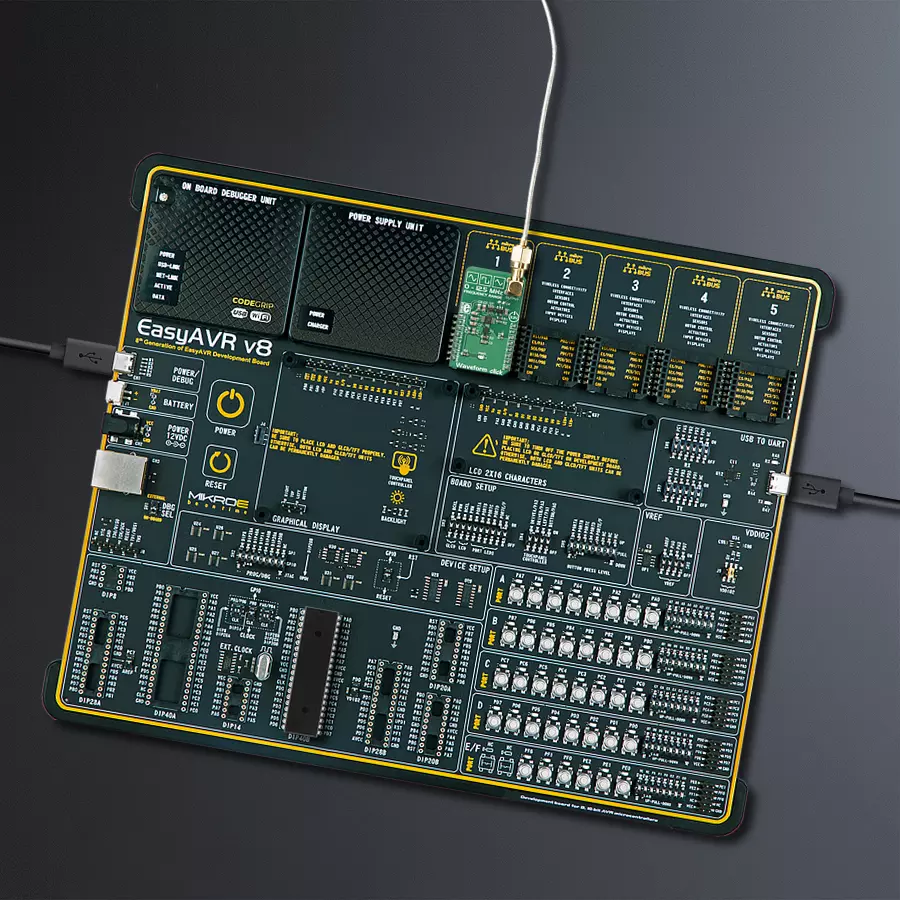
Development board
EasyAVR v8 is a development board designed to rapidly develop embedded applications based on 8-bit AVR microcontrollers (MCUs). Redesigned from the ground up, EasyAVR v8 offers a familiar set of standard features, as well as some new and unique features standard for the 8th generation of development boards: programming and debugging over the WiFi network, connectivity provided by USB-C connectors, support for a wide range of different MCUs, and more. The development board is designed so that the developer has everything that might be needed for the application development, following the Swiss Army knife concept: a highly advanced programmer/debugger module, a reliable power supply module, and a USB-UART connectivity option. EasyAVR v8 board offers several different DIP sockets, covering a wide range of 8-bit AVR MCUs, from the smallest
AVR MCU devices with only eight pins, all the way up to 40-pin "giants". The development board supports the well-established mikroBUS™ connectivity standard, offering five mikroBUS™ sockets, allowing access to a huge base of Click boards™. EasyAVR v8 offers two display options, allowing even the basic 8-bit AVR MCU devices to utilize them and display graphical or textual content. One of them is the 1x20 graphical display connector, compatible with the familiar Graphical Liquid Crystal Display (GLCD) based on the KS108 (or compatible) display driver, and EasyTFT board that contains TFT Color Display MI0283QT-9A, which is driven by ILI9341 display controller, capable of showing advanced graphical content. The other option is the 2x16 character LCD module, a four-bit display module with an embedded character-based display controller. It
requires minimal processing power from the host MCU for its operation. There is a wide range of useful interactive options at the disposal: high-quality buttons with selectable press levels, LEDs, pull-up/pulldown DIP switches, and more. All these features are packed on a single development board, which uses innovative manufacturing technologies, delivering a fluid and immersive working experience. The EasyAVR v8 development board is also integral to the MIKROE rapid development ecosystem. Natively supported by the MIKROE Software toolchain, backed up by hundreds of different Click board™ designs with their number growing daily, it covers many different prototyping and development aspects, thus saving precious development time.

Microcontroller Overview
MCU Card / MCU
Architecture
AVR
MCU Memory (KB)
32
Silicon Vendor
Microchip
Pin count
40
RAM (Bytes)
2048
Used MCU Pins
mikroBUS™ mapper
Take a closer look
Click board™ Schematic
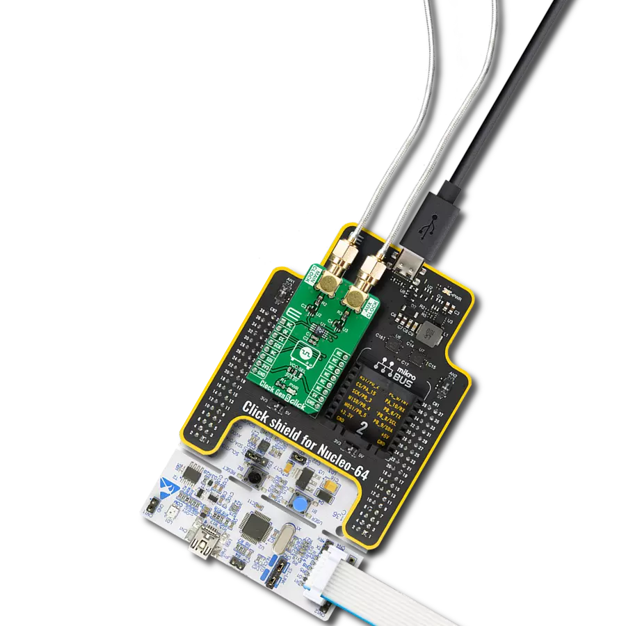
Step by step
Project assembly

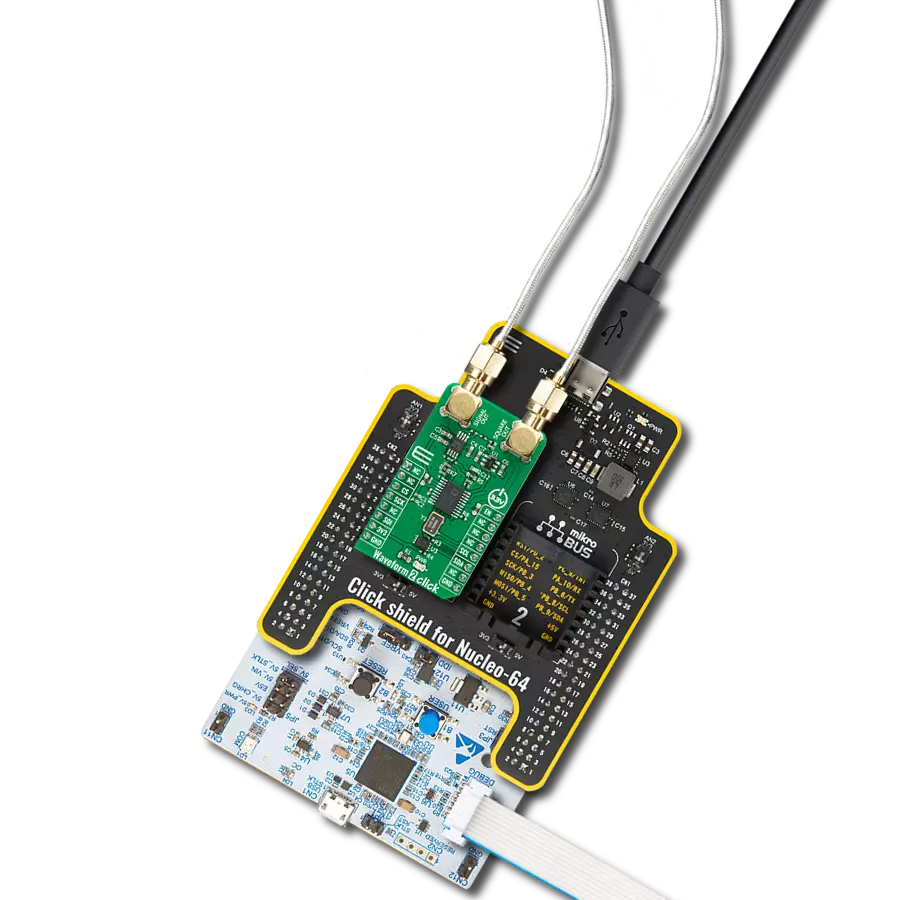
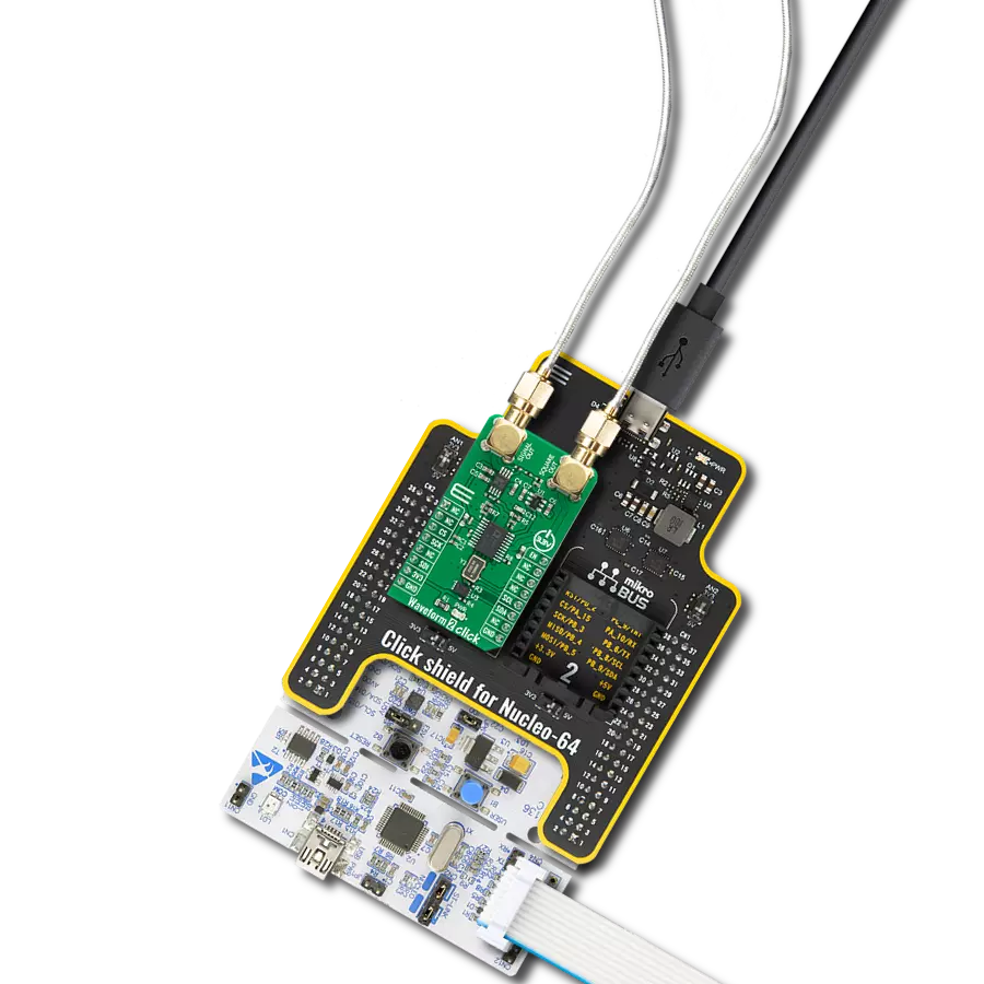
Start by selecting your development board and Click board™. Begin with the EasyAVR v8 as your development board.


Track your results in real time
Application Output
1. Application Output - In Debug mode, the 'Application Output' window enables real-time data monitoring, offering direct insight into execution results. Ensure proper data display by configuring the environment correctly using the provided tutorial.

2. UART Terminal - Use the UART Terminal to monitor data transmission via a USB to UART converter, allowing direct communication between the Click board™ and your development system. Configure the baud rate and other serial settings according to your project's requirements to ensure proper functionality. For step-by-step setup instructions, refer to the provided tutorial.

3. Plot Output - The Plot feature offers a powerful way to visualize real-time sensor data, enabling trend analysis, debugging, and comparison of multiple data points. To set it up correctly, follow the provided tutorial, which includes a step-by-step example of using the Plot feature to display Click board™ readings. To use the Plot feature in your code, use the function: plot(*insert_graph_name*, variable_name);. This is a general format, and it is up to the user to replace 'insert_graph_name' with the actual graph name and 'variable_name' with the parameter to be displayed.

Software Support
Library Description
This library contains API for Waveform Click driver.
Key functions:
waveform_sine_output- Sinusoide output functionwaveform_triangle_output- Triangle output functionwaveform_square_output- Square output function
Open Source
Code example
The complete application code and a ready-to-use project are available through the NECTO Studio Package Manager for direct installation in the NECTO Studio. The application code can also be found on the MIKROE GitHub account.
/*!
 * \file
 * \brief Waveform Click example
 *
 * # Description
 * This example demonstrates the use of Waveform Click board.
 *
 * The application is composed of two sections :
 *
 * ## Application Init
 * Initializes the communication interface and configures the Click board.
 *
 * ## Application Task
 * Predefined commands are inputed from the serial port.
 * Changes the signal frequency, waveform or amplitude depending on the receiver command.
 *
 * \author MikroE Team
 *
 */

#include "board.h"
#include "log.h"
#include "waveform.h"

static waveform_t waveform;
static log_t logger;

static uint32_t frequency = 200000;
static uint32_t frequency_step = 10000;

/**
 * @brief Waveform display commands function.
 * @details This function displays the list of supported commands on the USB UART.
 * @return None.
 * @note None.
 */
void waveform_display_commands ( void );

/**
 * @brief Waveform parse command function.
 * @details This function checks if the input command is supported and executes it.
 * @param[in] command : Command input, for more details refer to @b waveform_display_commands function.
 * @return None.
 * @note None.
 */
void waveform_parse_command ( uint8_t command );

void application_init ( void )
{
    log_cfg_t log_cfg;
    waveform_cfg_t waveform_cfg;

    /**
     * Logger initialization.
     * Default baud rate: 115200
     * Default log level: LOG_LEVEL_DEBUG
     * @note If USB_UART_RX and USB_UART_TX
     * are defined as HAL_PIN_NC, you will
     * need to define them manually for log to work.
     * See @b LOG_MAP_USB_UART macro definition for detailed explanation.
     */
    LOG_MAP_USB_UART( log_cfg );
    log_init( &logger, &log_cfg );
    log_info( &logger, " Application Init " );

    // Click initialization.
    waveform_cfg_setup( &waveform_cfg );
    WAVEFORM_MAP_MIKROBUS( waveform_cfg, MIKROBUS_1 );
    if ( SPI_MASTER_ERROR == waveform_init( &waveform, &waveform_cfg ) )
    {
        log_error( &logger, " Communication init." );
        for ( ; ; );
    }

    waveform_sine_output( &waveform, frequency );
    log_printf( &logger, "Sine wave output set with approx. frequency: %lu Hz\r\n", frequency );
    waveform_display_commands ( );
    log_info( &logger, " Application Task " );
}

void application_task ( void )
{
    uint8_t command = 0;
    if ( 1 == log_read ( &logger, &command, 1 ) )
    {
        waveform_parse_command ( command );
    }
}

int main ( void )
{
    /* Do not remove this line or clock might not be set correctly. */
    #ifdef PREINIT_SUPPORTED
    preinit();
    #endif

    application_init( );

    for ( ; ; )
    {
        application_task( );
    }

    return 0;
}

void waveform_display_commands ( void )
{
    log_printf( &logger, "-------------------------------------------\r\n" );
    log_info( &logger, "- UART commands list -\r\n" );
    log_printf( &logger, "'+' - Increase amplitude.\r\n" );
    log_printf( &logger, "'-' - Decrease amplitude.\r\n" );
    log_printf( &logger, "'S' - Select sine wave output and increase frequency.\r\n" );
    log_printf( &logger, "'s' - Select sine wave output and decrease frequency.\r\n" );
    log_printf( &logger, "'T' - Select triangle wave output and increase frequency.\r\n" );
    log_printf( &logger, "'t' - Select triangle wave output and decrease frequency.\r\n" );
    log_printf( &logger, "'Q' - Select square wave output and increase frequency.\r\n" );
    log_printf( &logger, "'q' - Select square wave output and decrease frequency.\r\n" );
    log_printf( &logger, "'L' or 'l' - Display commands list.\r\n" );
    log_printf( &logger, "-------------------------------------------\r\n" );
}

void waveform_parse_command ( uint8_t command )
{
    switch ( command )
    {
        case '+':
        {
            log_printf( &logger, "Increasing amplitude of the current wave.\r\n" );
            waveform_digipot_inc ( &waveform );
            break;
        }
        case '-':
        {
            log_printf( &logger, "Decreasing amplitude of the current wave.\r\n" );
            waveform_digipot_dec ( &waveform );
            break;
        }
        case 'S':
        {
            log_printf( &logger, "Increasing frequency of the sine wave.\r\n" );
            frequency += frequency_step;
            waveform_sine_output( &waveform, frequency );
            log_printf( &logger, "Approx. frequency: %lu Hz\r\n", frequency );
            break;
        }
        case 's':
        {
            log_printf( &logger, "Decreasing frequency of the sine wave.\r\n" );
            if ( frequency < frequency_step )
            {
                frequency = 0;
            }
            else
            {
                frequency -= frequency_step;
            }
            waveform_sine_output( &waveform, frequency );
            log_printf( &logger, "Approx. frequency: %lu Hz\r\n", frequency );
            break;
        }
        case 'T':
        {
            log_printf( &logger, "Increasing frequency of the triangle wave.\r\n" );
            frequency += frequency_step;
            waveform_triangle_output( &waveform, frequency );
            log_printf( &logger, "Approx. frequency: %lu Hz\r\n", frequency );
            break;
        }
        case 't':
        {
            log_printf( &logger, "Decreasing frequency of the triangle wave.\r\n" );
            if ( frequency < frequency_step )
            {
                frequency = 0;
            }
            else
            {
                frequency -= frequency_step;
            }
            waveform_triangle_output( &waveform, frequency );
            log_printf( &logger, "Approx. frequency: %lu Hz\r\n", frequency );
            break;
        }
        case 'Q':
        {
            log_printf( &logger, "Increasing frequency of the square wave.\r\n" );
            frequency += frequency_step;
            waveform_square_output( &waveform, frequency );
            log_printf( &logger, "Approx. frequency: %lu Hz\r\n", frequency );
            break;
        }
        case 'q':
        {
            log_printf( &logger, "Decreasing frequency of the square wave.\r\n" );
            if ( frequency < frequency_step )
            {
                frequency = 0;
            }
            else
            {
                frequency -= frequency_step;
            }
            waveform_square_output( &waveform, frequency );
            log_printf( &logger, "Approx. frequency: %lu Hz\r\n", frequency );
            break;
        }
        case 'L': case 'l':
        {
            waveform_display_commands ( );
            break;
        }
        default :
        {
            log_error( &logger, "Wrong command." );
            break;
        }
    }
}

// ------------------------------------------------------------------------ END
Additional Support
Resources
Category:Clock generator