Create your own air quality meter using iAQ-Core and STM32F031K6
Air quality monitoring made simple

Published Oct 01, 2024
Click board™
Air quality 2 Click
Dev. board
Nucleo 32 with STM32F031K6 MCU
Compiler
NECTO Studio
MCU
STM32F031K6
Join the movement for healthier air with our advanced air quality technology
A
A
Hardware Overview
How does it work?
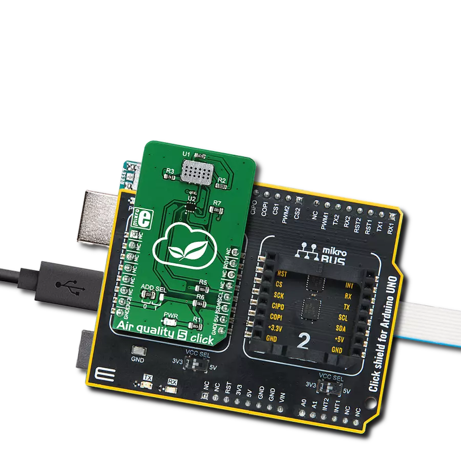
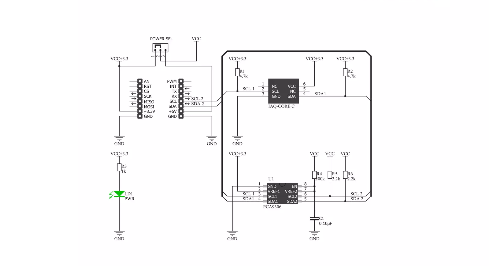
Air Quality 2 Click is based on the iAQ-Core Indoor Air Quality sensor from ScioSense that measures VOC (volatile organic compounds) levels and provides CO2 equivalent and TVOC (total volatile organic compounds) equivalent predictions. The click is designed to run on either a 3.3V or 5V power supply. It communicates with the target MCU over I2C. A plastic cap and a filter membrane protect the sensor. This membrane should not be removed or touched. The sensing range for CO2 equivalents is 450 to 2000 ppm (parts per million) and from 125 to 600 ppb (parts per billion) for TVOC equivalents. The first functional reading takes only 5 minutes after start-up time. After the sensor is powered on, you don't have to wait for it
to calibrate. You'll have all the readings you need in less time than it takes to make a cup of coffee. iAQ-Core sensor has Automatic Baseline Correction (ABC), which means that you don't need to make any further calibration. You can use it for many years in a normal indoor environment. With low power consumption (maximum of 9mW in pulsed mode and 66mW in continuous mode), Air Quality 2 Click is ideal for Smart Home applications and IoT projects and devices that require long battery life. Volatile organic compounds, or VOCs, are organic chemicals. They have very high vapor pressure at room temperature, and some can harm human health. These chemicals are carbon-based (formaldehyde,
toluene, benzene, and more) and are called "volatile" because they become gases at room temperature. They are emitted from various products, like hairspray, household cleaning products, paint, or air freshener, that we use daily. This Click board™ can operate with either 3.3V or 5V logic voltage levels selected via the PWR SEL jumper. This way, both 3.3V and 5V capable MCUs can use the communication lines properly. Also, this Click board™ comes equipped with a library containing easy-to-use functions and an example code that can be used as a reference for further development.


Features overview
Development board
Nucleo 32 with STM32F031K6 MCU board provides an affordable and flexible platform for experimenting with STM32 microcontrollers in 32-pin packages. Featuring Arduino™ Nano connectivity, it allows easy expansion with specialized shields, while being mbed-enabled for seamless integration with online resources. The
board includes an on-board ST-LINK/V2-1 debugger/programmer, supporting USB reenumeration with three interfaces: Virtual Com port, mass storage, and debug port. It offers a flexible power supply through either USB VBUS or an external source. Additionally, it includes three LEDs (LD1 for USB communication, LD2 for power,
and LD3 as a user LED) and a reset push button. The STM32 Nucleo-32 board is supported by various Integrated Development Environments (IDEs) such as IAR™, Keil®, and GCC-based IDEs like AC6 SW4STM32, making it a versatile tool for developers.

Microcontroller Overview
MCU Card / MCU

Architecture
ARM Cortex-M0
MCU Memory (KB)
32
Silicon Vendor
STMicroelectronics
Pin count
32
RAM (Bytes)
4096
You complete me!
Accessories
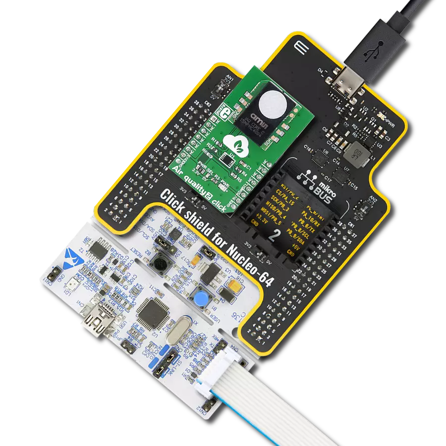
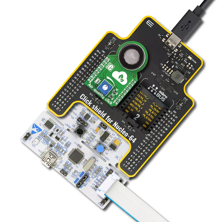
Click Shield for Nucleo-32 is the perfect way to expand your development board's functionalities with STM32 Nucleo-32 pinout. The Click Shield for Nucleo-32 provides two mikroBUS™ sockets to add any functionality from our ever-growing range of Click boards™. We are fully stocked with everything, from sensors and WiFi transceivers to motor control and audio amplifiers. The Click Shield for Nucleo-32 is compatible with the STM32 Nucleo-32 board, providing an affordable and flexible way for users to try out new ideas and quickly create prototypes with any STM32 microcontrollers, choosing from the various combinations of performance, power consumption, and features. The STM32 Nucleo-32 boards do not require any separate probe as they integrate the ST-LINK/V2-1 debugger/programmer and come with the STM32 comprehensive software HAL library and various packaged software examples. This development platform provides users with an effortless and common way to combine the STM32 Nucleo-32 footprint compatible board with their favorite Click boards™ in their upcoming projects.

Used MCU Pins
mikroBUS™ mapper
Take a closer look
Click board™ Schematic
Step by step
Project assembly

Start by selecting your development board and Click board™. Begin with the Nucleo 32 with STM32F031K6 MCU as your development board.


Track your results in real time
Application Output
1. Application Output - In Debug mode, the 'Application Output' window enables real-time data monitoring, offering direct insight into execution results. Ensure proper data display by configuring the environment correctly using the provided tutorial.

2. UART Terminal - Use the UART Terminal to monitor data transmission via a USB to UART converter, allowing direct communication between the Click board™ and your development system. Configure the baud rate and other serial settings according to your project's requirements to ensure proper functionality. For step-by-step setup instructions, refer to the provided tutorial.

3. Plot Output - The Plot feature offers a powerful way to visualize real-time sensor data, enabling trend analysis, debugging, and comparison of multiple data points. To set it up correctly, follow the provided tutorial, which includes a step-by-step example of using the Plot feature to display Click board™ readings. To use the Plot feature in your code, use the function: plot(*insert_graph_name*, variable_name);. This is a general format, and it is up to the user to replace 'insert_graph_name' with the actual graph name and 'variable_name' with the parameter to be displayed.

Software Support
Library Description
This library contains API for Air Quality 2 Click driver.
Key functions:
airquality2_generic_read- This function reads dataairquality2_get_all_data- Reads all data information about the indoor air quality
Open Source
Code example
The complete application code and a ready-to-use project are available through the NECTO Studio Package Manager for direct installation in the NECTO Studio. The application code can also be found on the MIKROE GitHub account.
/*!
 * \file
 * \brief Airquality2 Click example
 *
 * # Description
 * This app measure indoor air quality.
 *
 * The demo application is composed of two sections :
 *
 * ## Application Init
 * Initialization device.
 *
 * ## Application Task
 * This is a example which demonstrates the use of Air quality 2 Click board.
 * Read all data information about the indoor air quality
 * from register on the iAQ-Core module, display Prediction Value CO2 [ ppm ],
 * Prediction Value TVOC [ ppb ] and Resistance Value.
 * Results are being sent to the Usart Terminal where you can track their changes.
 * All data logs on usb uart for aproximetly every 5 sec.
 *
 * ## NOTE
 * The sensor is in warm-up phase when the status is RUNIN. The user should wait
 * for status OK in order to get valid data output.
 *
 * \author MikroE Team
 *
 */
// ------------------------------------------------------------------- INCLUDES

#include "board.h"
#include "log.h"
#include "airquality2.h"

// ------------------------------------------------------------------ VARIABLES

static airquality2_t airquality2;
static log_t logger;

// ------------------------------------------------------ APPLICATION FUNCTIONS

void application_init ( void )
{
    log_cfg_t log_cfg;
    airquality2_cfg_t cfg;

    /**
     * Logger initialization.
     * Default baud rate: 115200
     * Default log level: LOG_LEVEL_DEBUG
     * @note If USB_UART_RX and USB_UART_TX
     * are defined as HAL_PIN_NC, you will
     * need to define them manually for log to work.
     * See @b LOG_MAP_USB_UART macro definition for detailed explanation.
     */
    LOG_MAP_USB_UART( log_cfg );
    log_init( &logger, &log_cfg );
    log_info( &logger, "---- Application Init ----" );

    //  Click initialization.

    airquality2_cfg_setup( &cfg );
    AIRQUALITY2_MAP_MIKROBUS( cfg, MIKROBUS_1 );
    airquality2_init( &airquality2, &cfg );

    // Click calibration
    uint8_t dummy_buffer[ 9 ];
    airquality2_generic_read( &airquality2, dummy_buffer, AIRQUALITY2_READ_ALL );

    log_printf( &logger, "----------------------------------\r\n" );
    log_printf( &logger, "           Air quality 2          \r\n" );
    log_printf( &logger, "----------------------------------\r\n" );
    Delay_ms ( 100 );
}

void application_task ( void )
{
    uint8_t status_info;
    uint16_t value_co2;
    uint16_t value_tvoc;
    int32_t resistance;

    status_info = airquality2_get_all_data( &airquality2, &value_co2, &value_tvoc, &resistance );
    Delay_100ms( );

    if ( status_info == AIRQUALITY2_STATUS_OK )
    {
        log_printf( &logger, "       | Status : OK     |\r\n" );
    }
    if ( status_info == AIRQUALITY2_STATUS_BUSY )
    {
        log_printf( &logger, "       | Status : BUSY   |\r\n" );
    }
    if ( status_info == AIRQUALITY2_STATUS_ERROR )
    {
        log_printf( &logger, "       | Status : ERROR  |\r\n" );
    }
    if ( status_info == AIRQUALITY2_STATUS_RUNIN )
    {
        log_printf( &logger, "       | Status : RUNIN  |\r\n" );
    }

    log_printf( &logger, "----------------------------------\r\n" );

    log_printf( &logger, " CO2        : %u [ ppm ] \r\n", value_co2 );

    log_printf( &logger, " TVOC       : %u [ ppb ] \r\n", value_tvoc );

    log_printf( &logger, " Resistance : %ld [ Ohm ] \r\n", resistance );

    log_printf( &logger, "----------------------------------\r\n" );

    Delay_1sec( );
    Delay_1sec( );
    Delay_1sec( );
    Delay_1sec( );
    Delay_1sec( );
}

int main ( void )
{
    /* Do not remove this line or clock might not be set correctly. */
    #ifdef PREINIT_SUPPORTED
    preinit();
    #endif

    application_init( );

    for ( ; ; )
    {
        application_task( );
    }

    return 0;
}

// ------------------------------------------------------------------------ END
Additional Support
Resources
Category:Gas