Say hello to clean air with ZMOD4510 and STM32F031K6
Guardians of Freshness: Our solution, your healthier reality

Published Oct 01, 2024
Click board™
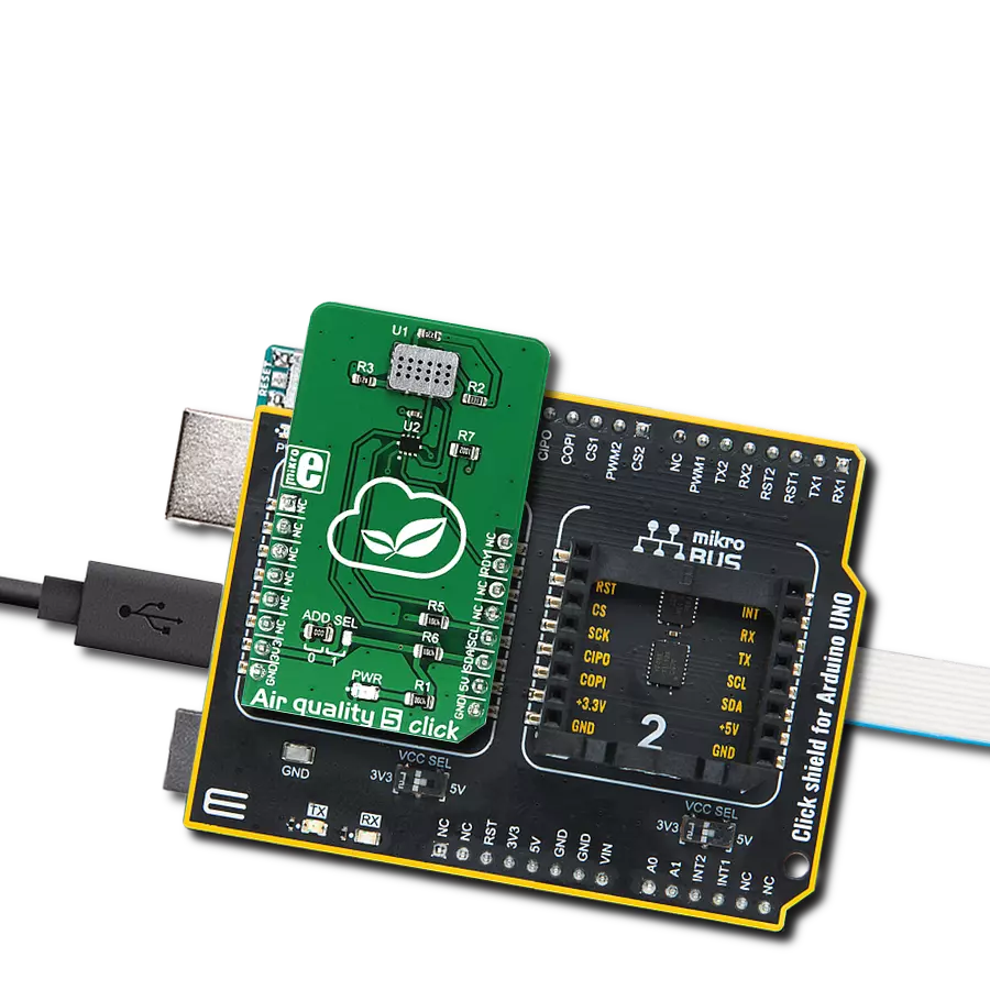
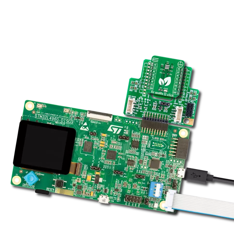
Air quality 8 Click
Dev. board
Nucleo 32 with STM32F031K6 MCU
Compiler
NECTO Studio
MCU
STM32F031K6
Designed to address the growing concern of air pollution, our monitor solution acts as a guardian, ensuring the air you breathe is of the highest quality
A
A
Hardware Overview
How does it work?
Air quality 8 Click is based on the ZMOD4510, a pre-calibrated digital sensor designed for reliable indoor and outdoor air quality detection from Renesas. This sensor comes with selective ozone measurement capabilities (NO2 and O3) and allows improved energy efficiency with less than 23mW of power consumption in continuous operation without compromising air quality. It also features electrical and gas calibration, proven MOx material, a digital interface, siloxane resistance, high sensitivity, and long-term stability, allowing ppb detection limits. It covers extended operating humidity and temperature ranges from 5 to 90%RH and from -20°C to 50°C with ozone and nitrogen dioxide measurement ranges from 20 to 500ppb. The ZMOD4510 has a gas-sense element consisting of a heater element on a silicon-based MEMS structure, a metal-oxide (MOx) chemiresistor, and a CMOS signal conditioning IC that controls the sensor temperature and
measures the MOx resistance, which is a function of the gas concentration. It has two operational modes. The first mode of operation allows a general measurement of Air Quality, including the non-selective measurement of nitrogen dioxide (NO2) and ozone (O3). The second mode of operation allows the selective measurement of ozone (O3) featuring Ultra-Low Power with an average consumption of 0.2mW during its fast sample rate of 2 seconds. It detects typical gases based on studies and international standards for outdoor air quality and uses a sequence of applied temperatures to sample the air and report an Air Quality Index (AQI). The sensor does not require an active or direct airflow onto the sensor module because diffusion of ambient gas does not limit the sensor response time. The ZMOD4510 can also detect safety-relevant gases; however, the sensor module is not designed to detect these interferants reliably. Therefore, it is not approved
for use in safety-critical or life-protecting applications. Air quality 8 Click communicates with MCU using the standard I2C 2-Wire interface to read data and configure settings, supporting Standard Mode operation with a clock frequency of 100kHz and Fast Mode up to 400kHz. In addition, it also possesses other features such as a reset pin routed to the RST pin on the mikroBUS™ socket, which with a low logic level puts the module into a Reset state, an additional interrupt signal routed on the INT pin of the mikroBUS™ socket labeled as INT, indicating the status of measurement process itself. This Click board™ can be operated only with a 3.3V logic voltage level. The board must perform appropriate logic voltage level conversion before using MCUs with different logic levels. Also, it comes equipped with a library containing functions and an example code that can be used as a reference for further development.


Features overview
Development board
Nucleo 32 with STM32F031K6 MCU board provides an affordable and flexible platform for experimenting with STM32 microcontrollers in 32-pin packages. Featuring Arduino™ Nano connectivity, it allows easy expansion with specialized shields, while being mbed-enabled for seamless integration with online resources. The
board includes an on-board ST-LINK/V2-1 debugger/programmer, supporting USB reenumeration with three interfaces: Virtual Com port, mass storage, and debug port. It offers a flexible power supply through either USB VBUS or an external source. Additionally, it includes three LEDs (LD1 for USB communication, LD2 for power,
and LD3 as a user LED) and a reset push button. The STM32 Nucleo-32 board is supported by various Integrated Development Environments (IDEs) such as IAR™, Keil®, and GCC-based IDEs like AC6 SW4STM32, making it a versatile tool for developers.

Microcontroller Overview
MCU Card / MCU

Architecture
ARM Cortex-M0
MCU Memory (KB)
32
Silicon Vendor
STMicroelectronics
Pin count
32
RAM (Bytes)
4096
You complete me!
Accessories
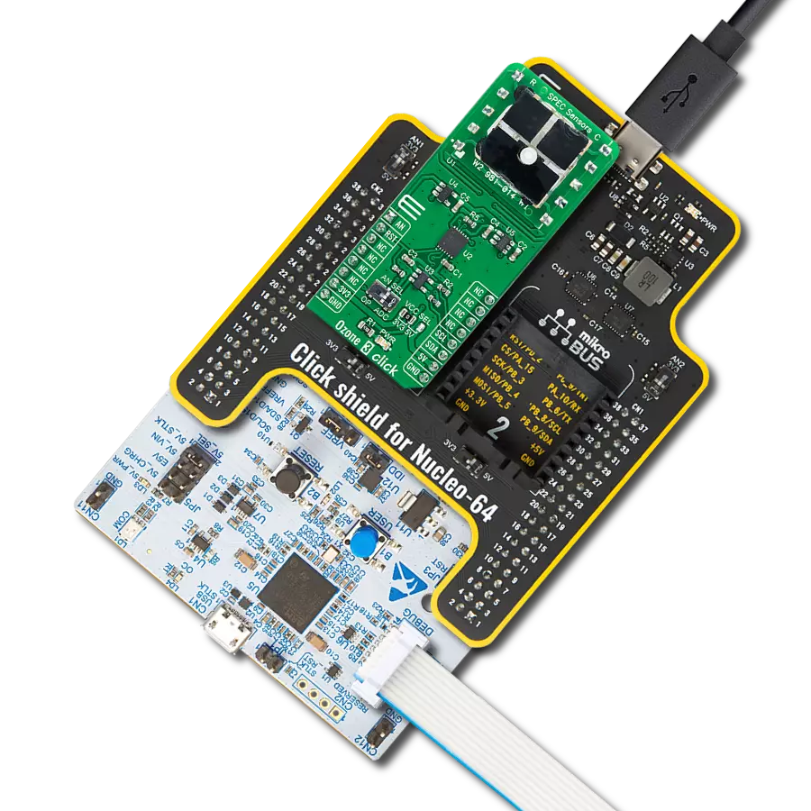
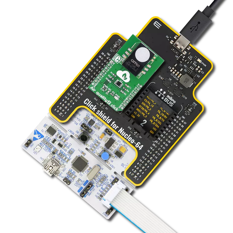
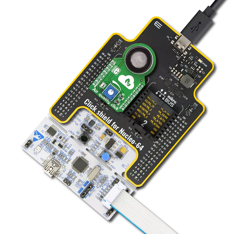
Click Shield for Nucleo-32 is the perfect way to expand your development board's functionalities with STM32 Nucleo-32 pinout. The Click Shield for Nucleo-32 provides two mikroBUS™ sockets to add any functionality from our ever-growing range of Click boards™. We are fully stocked with everything, from sensors and WiFi transceivers to motor control and audio amplifiers. The Click Shield for Nucleo-32 is compatible with the STM32 Nucleo-32 board, providing an affordable and flexible way for users to try out new ideas and quickly create prototypes with any STM32 microcontrollers, choosing from the various combinations of performance, power consumption, and features. The STM32 Nucleo-32 boards do not require any separate probe as they integrate the ST-LINK/V2-1 debugger/programmer and come with the STM32 comprehensive software HAL library and various packaged software examples. This development platform provides users with an effortless and common way to combine the STM32 Nucleo-32 footprint compatible board with their favorite Click boards™ in their upcoming projects.

Used MCU Pins
mikroBUS™ mapper
Take a closer look
Click board™ Schematic

Step by step
Project assembly

Start by selecting your development board and Click board™. Begin with the Nucleo 32 with STM32F031K6 MCU as your development board.


Track your results in real time
Application Output
1. Application Output - In Debug mode, the 'Application Output' window enables real-time data monitoring, offering direct insight into execution results. Ensure proper data display by configuring the environment correctly using the provided tutorial.

2. UART Terminal - Use the UART Terminal to monitor data transmission via a USB to UART converter, allowing direct communication between the Click board™ and your development system. Configure the baud rate and other serial settings according to your project's requirements to ensure proper functionality. For step-by-step setup instructions, refer to the provided tutorial.

3. Plot Output - The Plot feature offers a powerful way to visualize real-time sensor data, enabling trend analysis, debugging, and comparison of multiple data points. To set it up correctly, follow the provided tutorial, which includes a step-by-step example of using the Plot feature to display Click board™ readings. To use the Plot feature in your code, use the function: plot(*insert_graph_name*, variable_name);. This is a general format, and it is up to the user to replace 'insert_graph_name' with the actual graph name and 'variable_name' with the parameter to be displayed.

Software Support
Library Description
This library contains API for Air Quality 8 Click driver.
Key functions:
airquality8_calc_oaq- Air Quality 8 calculates AQI functionairquality8_read_rmox- Air Quality 8 calculate rmox resistance functionairquality8_start_measurement- Air Quality 8 start measurement function
Open Source
Code example
The complete application code and a ready-to-use project are available through the NECTO Studio Package Manager for direct installation in the NECTO Studio. The application code can also be found on the MIKROE GitHub account.
/*!
 * @file main.c
 * @brief AirQuality8 Click example
 *
 * # Description
 * This library contains API for Air Quality 8 Click driver.
 * The library initializes and defines the I2C bus drivers
 * to write and read data from registers.
 * The library also includes a function for configuring sensor and measurement,
 * read and calculate mox resistance ( RMOX ) and air quality index ( AQI ), etc.
 *
 * The demo application is composed of two sections :
 *
 * ## Application Init
 * Initialization of I2C module and log UART, and additional pins.
 * After the driver inits and executes a default configuration,
 * the app read product ID and configuration parameters,
 * initializes the sensor and measurement.
 *
 * ## Application Task
 * This is an example that demonstrates the use of the Air Quality 8 Click board™.
 * In this example, the app performs the start of the measurement,
 * reads an array of the 15 mox resistances measurements ( RMOX ),
 * and calculates the air quality index ( AQI ), the app also, displays if an error occurs.
 * Results are being sent to the Usart Terminal where you can track their changes.
 *
 * ## Additional Function
 * - static void display_error ( void )
 *
 * @author Nenad Filipovic
 *
 */

#include "board.h"
#include "log.h"
#include "airquality8.h"

static airquality8_t airquality8;
static log_t logger;
static uint16_t mox_lr;
static uint16_t mox_er;
static uint8_t status_flag;

static void display_error ( void )
{
    if ( status_flag == AIRQUALITY8_ERROR_INIT_OUT_OF_RANGE )
    {
        log_printf( &logger, " The initialize value is out of range.\r\n" );
    }

    if ( status_flag == AIRQUALITY8_ERROR_GAS_TIMEOUT )
    {
        log_printf( &logger, " The operation took too long.\r\n" );
    }

    if ( status_flag == AIRQUALITY8_ERROR_I2C )
    {
        log_printf( &logger, " Failure in i2c communication.\r\n" );
    }

    if ( status_flag == AIRQUALITY8_ERROR_SENSOR_UNSUPPORTED )
    {
        log_printf( &logger, " Sensor is not supported with this firmware.\r\n" );
    }

    if ( status_flag == AIRQUALITY8_ERROR_CONFIG_MISSING )
    {
        log_printf( &logger, " There is no pointer to a valid configuration.\r\n" );
    }

    if ( status_flag == AIRQUALITY8_ERROR_SENSOR )
    {
        log_printf( &logger, " Sensor malfunction.\r\n" );
    }
}

void application_init ( void )
{
    log_cfg_t log_cfg;  /**< Logger config object. */
    airquality8_cfg_t airquality8_cfg;  /**< Click config object. */

    /**
     * Logger initialization.
     * Default baud rate: 115200
     * Default log level: LOG_LEVEL_DEBUG
     * @note If USB_UART_RX and USB_UART_TX
     * are defined as HAL_PIN_NC, you will
     * need to define them manually for log to work.
     * See @b LOG_MAP_USB_UART macro definition for detailed explanation.
     */
    LOG_MAP_USB_UART( log_cfg );
    log_init( &logger, &log_cfg );
    log_info( &logger, " Application Init " );

    // Click initialization.
    airquality8_cfg_setup( &airquality8_cfg );
    AIRQUALITY8_MAP_MIKROBUS( airquality8_cfg, MIKROBUS_1 );
    if ( I2C_MASTER_ERROR == airquality8_init( &airquality8, &airquality8_cfg ) )
    {
        log_error( &logger, " Communication init." );
        for ( ; ; );
    }

    if ( AIRQUALITY8_ERROR == airquality8_default_cfg ( &airquality8 ) )
    {
        log_error( &logger, " Default configuration." );
        for ( ; ; );
    }
    Delay_ms ( 100 );

    static uint8_t cfg_data[ 6 ];
    static uint8_t prod_data[ 5 ];
    static uint16_t pid;

    airquality8_get_sensor_info( &airquality8, &cfg_data[ 0 ], &prod_data[ 0 ], &pid );

    if ( pid != AIRQUALITY8_PRODUCT_ID )
    {
        status_flag = AIRQUALITY8_ERROR_I2C;
        display_error( );
        for ( ; ; );
    }
    Delay_ms ( 100 );

    log_printf( &logger, "---------------------------\r\n" );
    log_printf( &logger, " Product ID : 0x%.2X  \r\n", pid );
    Delay_ms ( 100 );

    airquality8_init_sensor( &airquality8, &mox_lr, &mox_er );
    Delay_ms ( 10 );

    airquality8_init_measurement( &airquality8 );
    Delay_ms ( 10 );

    log_printf( &logger, "---------------------------\r\n" );
    log_info( &logger, " Application Task " );
    log_printf( &logger, "---------------------------\r\n" );
    log_printf( &logger, "      Air Quality Index\r\n" );
    log_printf( &logger, "- - - - - - - - - - - - - -\r\n" );
    Delay_ms ( 100 );
}

void application_task ( void )
{
    static uint8_t status_data;
    static float rmox;
    static float rmox_seq[ 15 ];
    static float aqi;

    status_flag = airquality8_start_measurement( &airquality8 );

    airquality8_get_status( &airquality8, &status_data );
    Delay_ms ( 10 );

    while ( ( status_data & AIRQUALITY8_STATUS_LAST_SEQ_STEP_MASK ) != AIRQUALITY8_OK )
    {
        airquality8_get_status( &airquality8, &status_data );
        Delay_ms ( 10 );
    }

    for ( uint8_t n_cnt = 0; n_cnt < 15; n_cnt++ )
    {
        status_flag = airquality8_read_rmox( &airquality8, &rmox, mox_lr, mox_er );
        rmox_seq[ n_cnt ] = rmox;
        Delay_ms ( 100 );

        if ( status_flag != AIRQUALITY8_OK )
        {
            display_error( );
        }
    }

    aqi = airquality8_calc_oaq( rmox_seq, AIRQUALITY8_RCDA_STRATEGY_ADJ, AIRQUALITY8_GAS_DETECTION_STRATEGY_AUTO );
    log_printf( &logger, " \tAQI : %.3f \r\n", aqi );
    log_printf( &logger, "---------------------------\r\n" );
    Delay_ms ( 1000 );
}

int main ( void )
{
    /* Do not remove this line or clock might not be set correctly. */
    #ifdef PREINIT_SUPPORTED
    preinit();
    #endif

    application_init( );

    for ( ; ; )
    {
        application_task( );
    }

    return 0;
}

// ------------------------------------------------------------------------ END
Additional Support
Resources
Category:Gas