Create custom buck conversion for optimized performance with TPS568215 and STM32F031K6
Energy in your pocket!
Published Oct 01, 2024
Click board™
Buck 3 click
Dev. board
Nucleo 32 with STM32F031K6 MCU
Compiler
NECTO Studio
MCU
STM32F031K6
Efficiently lower the input voltage to match the desired output, conserving energy in the process
A
A
Hardware Overview
How does it work?
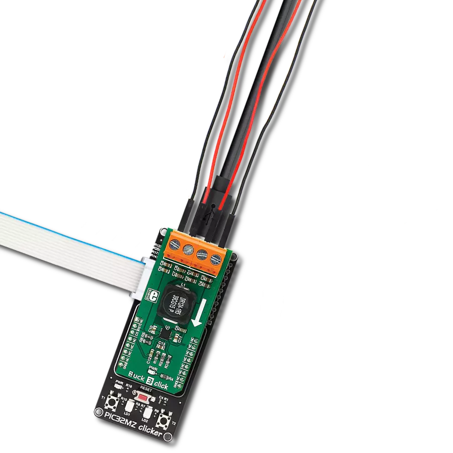
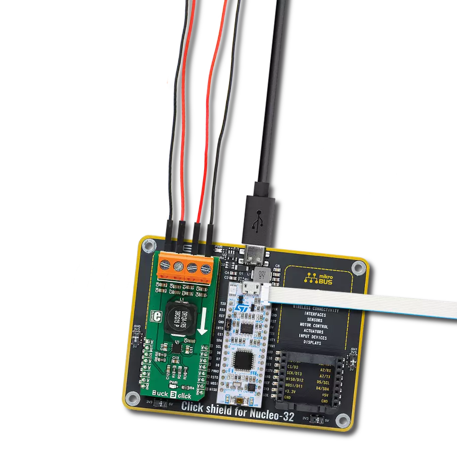
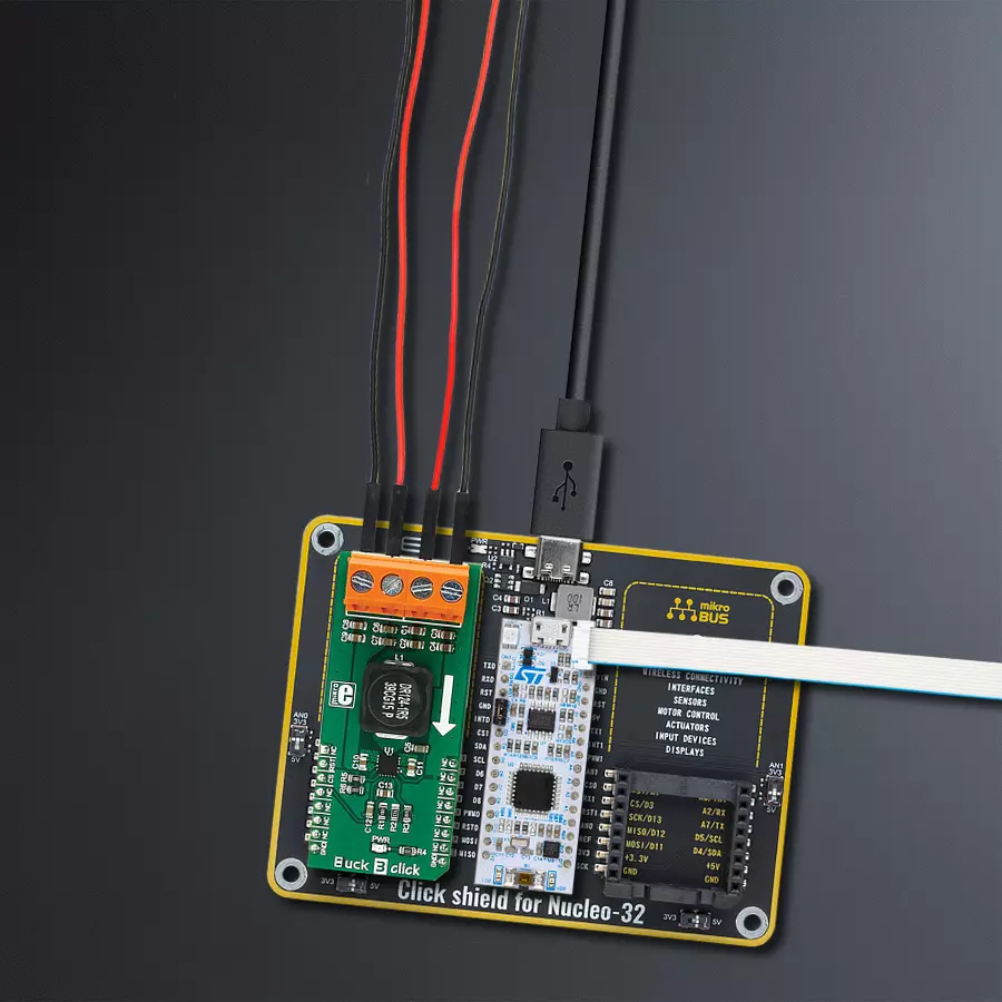
Buck 3 Click is based on the TPS568215, a 4.5V to 17V Input, 8A synchronous step-down SWIFT™ converter from Texas Instruments. Its main features are unparalleled ripple and noise-free operation and high efficiency throughout the whole load range, up to 8A. As such, it is suitable for powering up power-demanding applications. Driven by the D-CAP3™ technology, the TPS568215 allows for a low number of external components, maintaining an accurate voltage at the output. To further minimize the noise, the TPS568215 has separate grounds for the logic and analog signals. The design of the Click board™ PCB ensures that the low noise operation is maintained within the specifications. The onboard voltage divider connected to the MODE pin of the IC is used to set the device to work with the fixed PWM frequency of 800kHz, DCM/Eco-mode™ for light loads, and to
set the limiting current to about 7A. When the connected load is light enough, the ripple current valleys on the inductor coils will cross zero. Since the TPS568215 is set to operate in DCM/Eco-mode™, the device will start skipping PWM pulses, maintaining efficiency. The device will be operated with the fixed frequency PWM signal, set by the MODE pin - 800kHz, providing low ripple and noise output voltage for regular loads. The PGD (power good) pin is used to signalize the undervoltage or overvoltage status of the device. When the voltage on the feedback pin is between 97% and 107% of the nominal output voltage, this pin is de-asserted and pulled to a HIGH logic level by the onboard pull-up resistor. This pin is driven to a LOW logic state when a faulty condition occurs. PGD pin is routed to the CS pin of the mikroBUS™. The EN pin is used to enable the
device. Setting this pin to a HIGH logic level (above 1.2V) will activate the internal switching circuitry. When the pin is set to a LOW logic level, the device is in STANDBY mode, with minimal power consumption. The EN pin is routed to the mikroBUS™ AN pin. This Click board™ is not powered up by the mikroBUS™ power rails. The internal LDO output from the TPS568215 (VREG) supplies the power for the logic sections of the IC. The input voltage supplies this internal LDO, so the Buck 3 Click will appear unpowered unless the external power supply is connected to the input terminal. Buck 3 click has two 2-pole terminals used to connect the external power supply and the load. These robust input and output screw terminals have cross-section dimensions that allow high currents to be connected with no heating or damage.

Features overview
Development board
Nucleo 32 with STM32F031K6 MCU board provides an affordable and flexible platform for experimenting with STM32 microcontrollers in 32-pin packages. Featuring Arduino™ Nano connectivity, it allows easy expansion with specialized shields, while being mbed-enabled for seamless integration with online resources. The
board includes an on-board ST-LINK/V2-1 debugger/programmer, supporting USB reenumeration with three interfaces: Virtual Com port, mass storage, and debug port. It offers a flexible power supply through either USB VBUS or an external source. Additionally, it includes three LEDs (LD1 for USB communication, LD2 for power,
and LD3 as a user LED) and a reset push button. The STM32 Nucleo-32 board is supported by various Integrated Development Environments (IDEs) such as IAR™, Keil®, and GCC-based IDEs like AC6 SW4STM32, making it a versatile tool for developers.

Microcontroller Overview
MCU Card / MCU

Architecture
ARM Cortex-M0
MCU Memory (KB)
32
Silicon Vendor
STMicroelectronics
Pin count
32
RAM (Bytes)
4096
You complete me!
Accessories
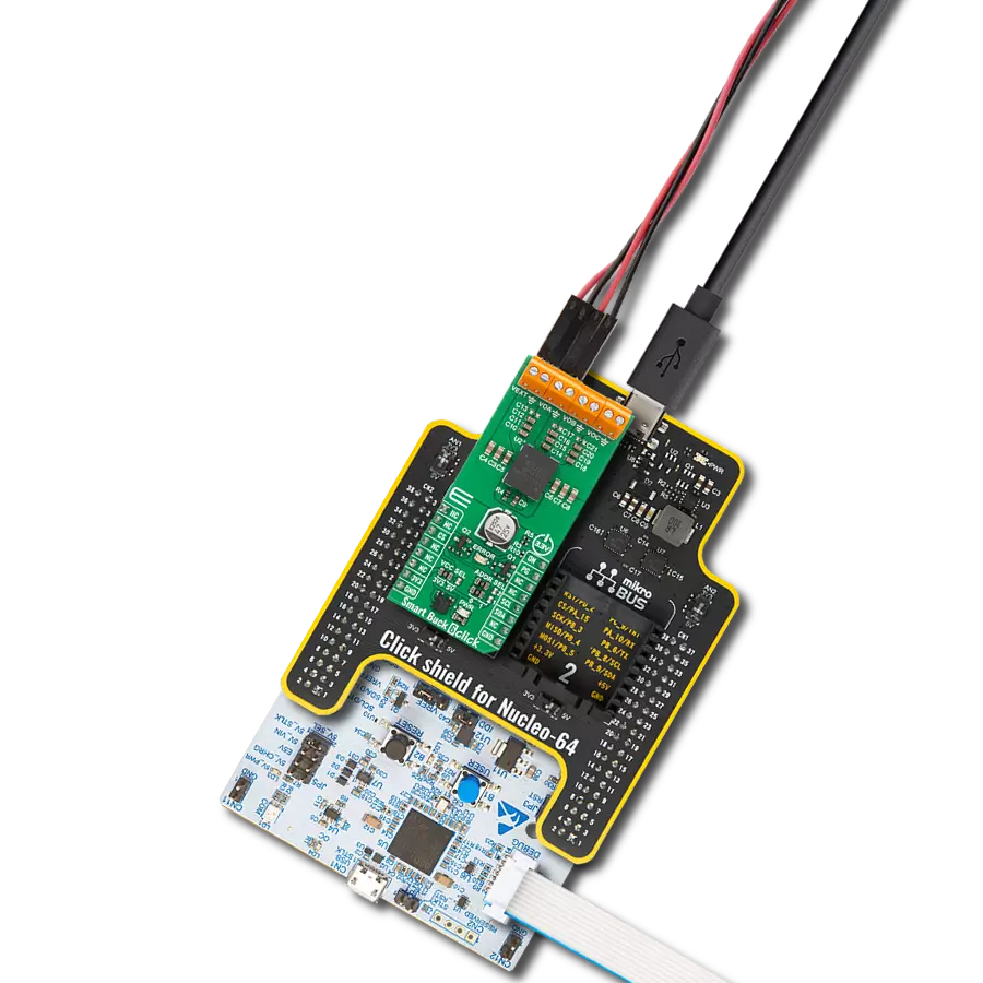
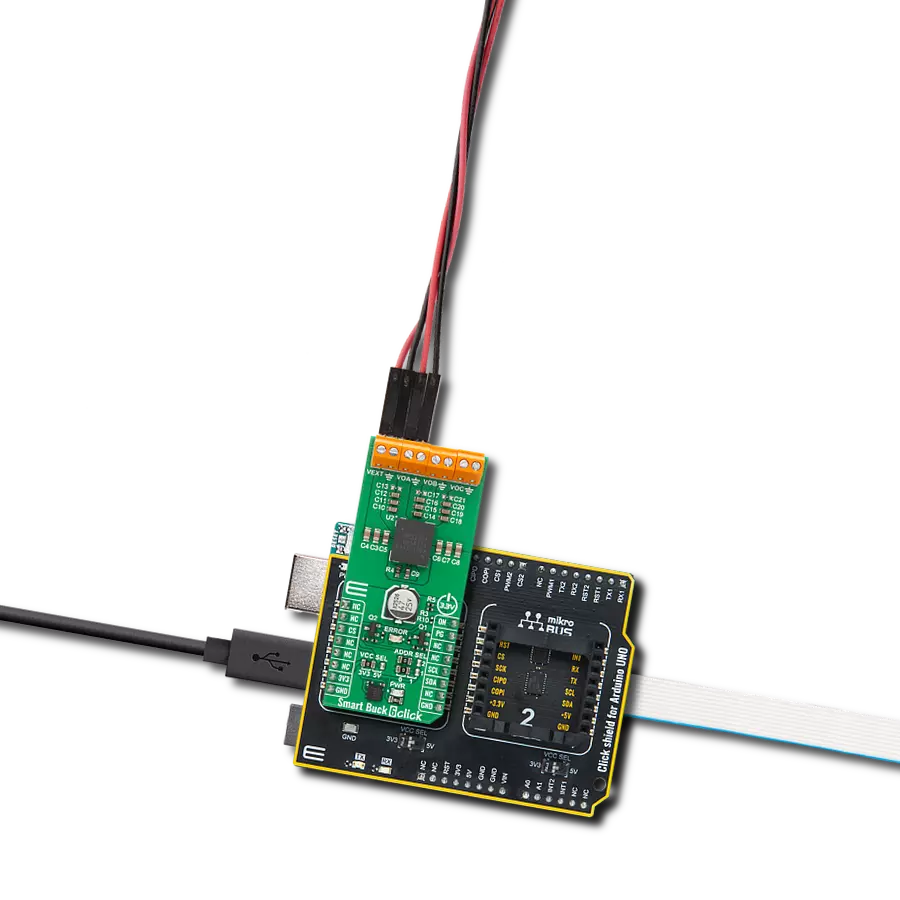
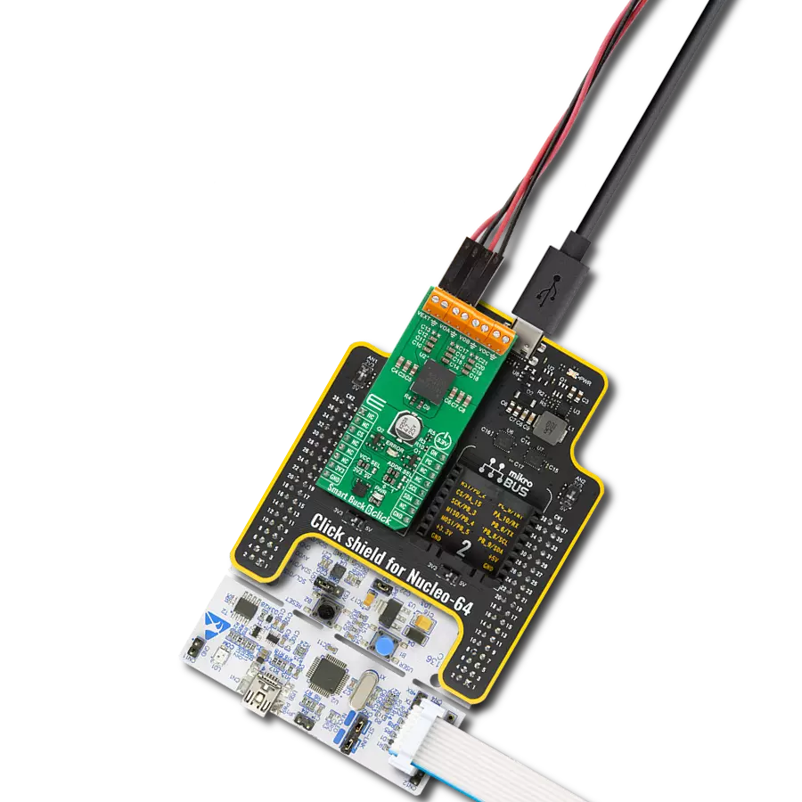
Click Shield for Nucleo-32 is the perfect way to expand your development board's functionalities with STM32 Nucleo-32 pinout. The Click Shield for Nucleo-32 provides two mikroBUS™ sockets to add any functionality from our ever-growing range of Click boards™. We are fully stocked with everything, from sensors and WiFi transceivers to motor control and audio amplifiers. The Click Shield for Nucleo-32 is compatible with the STM32 Nucleo-32 board, providing an affordable and flexible way for users to try out new ideas and quickly create prototypes with any STM32 microcontrollers, choosing from the various combinations of performance, power consumption, and features. The STM32 Nucleo-32 boards do not require any separate probe as they integrate the ST-LINK/V2-1 debugger/programmer and come with the STM32 comprehensive software HAL library and various packaged software examples. This development platform provides users with an effortless and common way to combine the STM32 Nucleo-32 footprint compatible board with their favorite Click boards™ in their upcoming projects.

Used MCU Pins
mikroBUS™ mapper
Take a closer look
Click board™ Schematic

Step by step
Project assembly

Start by selecting your development board and Click board™. Begin with the Nucleo 32 with STM32F031K6 MCU as your development board.


Track your results in real time
Application Output
1. Application Output - In Debug mode, the 'Application Output' window enables real-time data monitoring, offering direct insight into execution results. Ensure proper data display by configuring the environment correctly using the provided tutorial.

2. UART Terminal - Use the UART Terminal to monitor data transmission via a USB to UART converter, allowing direct communication between the Click board™ and your development system. Configure the baud rate and other serial settings according to your project's requirements to ensure proper functionality. For step-by-step setup instructions, refer to the provided tutorial.

3. Plot Output - The Plot feature offers a powerful way to visualize real-time sensor data, enabling trend analysis, debugging, and comparison of multiple data points. To set it up correctly, follow the provided tutorial, which includes a step-by-step example of using the Plot feature to display Click board™ readings. To use the Plot feature in your code, use the function: plot(*insert_graph_name*, variable_name);. This is a general format, and it is up to the user to replace 'insert_graph_name' with the actual graph name and 'variable_name' with the parameter to be displayed.

Software Support
Library Description
This library contains API for Buck 3 Click driver.
Key functions:
buck3_set_device_state- Function for setting device modebuck3_get_power_good- Function reads state of PGD pin
Open Source
Code example
The complete application code and a ready-to-use project are available through the NECTO Studio Package Manager for direct installation in the NECTO Studio. The application code can also be found on the MIKROE GitHub account.
/*!
 * \file
 * \brief Buck 3 Click example
 *
 * # Description
 * This example demonstrates the use of Buck 3 Click board.
 *
 * The demo application is composed of two sections :
 *
 * ## Application Init
 * Initializes the driver and configures the Click board.
 *
 * ## Application Task
 * Checks the PGD pin state which signalize the undervoltage or overvoltage fault or
 * the thermal shutdown condition.
 * If there's any of the above faults detected it logs a desired message on USB UART.
 *
 * \author Katarina Perendic
 *
 */
// ------------------------------------------------------------------- INCLUDES

#include "board.h"
#include "log.h"
#include "buck3.h"

// ------------------------------------------------------------------ VARIABLES

static buck3_t buck3;
static log_t logger;

// ------------------------------------------------------ APPLICATION FUNCTIONS

void application_init ( void )
{
    log_cfg_t log_cfg;
    buck3_cfg_t cfg;

    /**
     * Logger initialization.
     * Default baud rate: 115200
     * Default log level: LOG_LEVEL_DEBUG
     * @note If USB_UART_RX and USB_UART_TX
     * are defined as HAL_PIN_NC, you will
     * need to define them manually for log to work.
     * See @b LOG_MAP_USB_UART macro definition for detailed explanation.
     */
    LOG_MAP_USB_UART( log_cfg );
    log_init( &logger, &log_cfg );
    log_info( &logger, "---- Application Init ----" );

    //  Click initialization.

    buck3_cfg_setup( &cfg );
    BUCK3_MAP_MIKROBUS( cfg, MIKROBUS_1 );
    buck3_init( &buck3, &cfg );

    buck3_default_cfg( &buck3 );
    log_info( &logger, "---- Buck 3 is activated ----" );
    Delay_1sec( );
}

void application_task ( void )
{
    if ( !buck3_get_power_good( &buck3 ) )
    {
        log_info ( &logger, "---- Overvoltage or thermal shutdown detected ----" );
    }
    Delay_1sec( );
}

int main ( void )
{
    /* Do not remove this line or clock might not be set correctly. */
    #ifdef PREINIT_SUPPORTED
    preinit();
    #endif

    application_init( );

    for ( ; ; )
    {
        application_task( );
    }

    return 0;
}


// ------------------------------------------------------------------------ END
Additional Support
Resources
Category:Buck