Experience the power of touch with CY8C201A0 and STM32F031K6
Tap into innovation

Published Oct 01, 2024
Click board™
CapSense Click
Dev. board
Nucleo 32 with STM32F031K6 MCU
Compiler
NECTO Studio
MCU
STM32F031K6
Experience intuitive interaction like never before by integrating responsive touch controls into your projects for enhanced user experiences and functionality
A
A
Hardware Overview
How does it work?
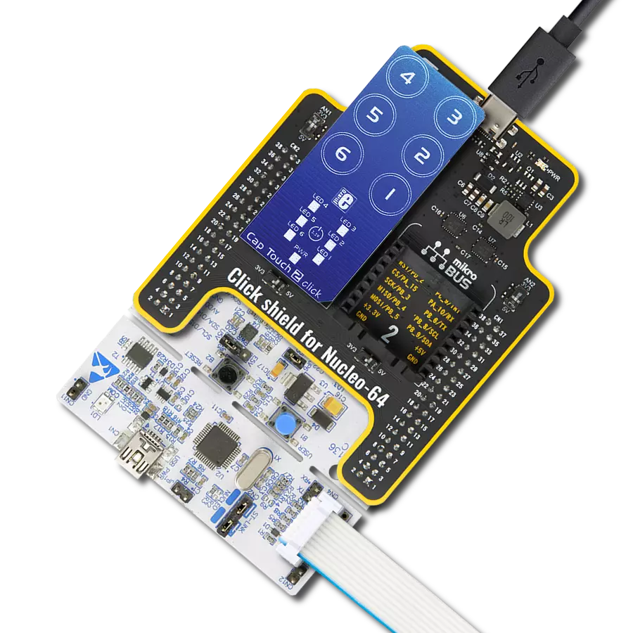
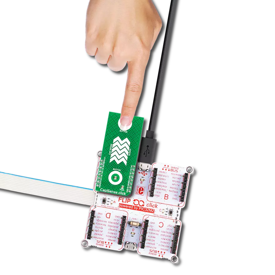
CapSense Click is based on the CY8C201A0, a multi-channel capacitive touch sensor from Infineon Technologies. The CY8C201A0 takes human body capacitance as an input and directly provides real-time sensor information via a serial interface. The user can also configure registers with parameters needed to adjust the operation and sensitivity of the CapSense touch buttons and slider and permanently store the settings. As mentioned earlier, this board contains a 5-segment capacitive sensing slider that can detect a slide in either the UP or DOWN direction, as well as two touch button pads which are the only elements on the top side of the board. Each of these touch button pads has a
LED indicator representing the activity in that field. If a touch event is detected on one of these onboard pads, the state of the corresponding LED will be changed, indicating an activated channel; more precisely, touch has been detected on that specific field. CapSense Click communicates with MCU using the standard I2C 2-Wire interface to read data and configure settings. The CY8C201A0 contains multiple operating modes: Active, Periodic Sleep, and Deep Sleep Mode, to meet different power consumption requirements. In the case of using some of the existing Sleep modes, the user is provided with the possibility of controlling these states via the GPO pin, routed to the AN pin of the
mikroBUS™ socket, or this pin can be set in software as an interrupt pin indicating when a specific interrupt event occurs (touch detection). Besides, a Reset pin, routed to the RST pin of the mikroBUS™ socket, causes all operations of the CY8C201A0s CPU and blocks to stop and return to a pre-defined state. This Click board™ can operate with either 3.3V or 5V logic voltage levels selected via the PWR SEL jumper. This way, both 3.3V and 5V capable MCUs can use the communication lines properly. However, the Click board™ comes equipped with a library containing easy-to-use functions and an example code that can be used, as a reference, for further development.

Features overview
Development board
Nucleo 32 with STM32F031K6 MCU board provides an affordable and flexible platform for experimenting with STM32 microcontrollers in 32-pin packages. Featuring Arduino™ Nano connectivity, it allows easy expansion with specialized shields, while being mbed-enabled for seamless integration with online resources. The
board includes an on-board ST-LINK/V2-1 debugger/programmer, supporting USB reenumeration with three interfaces: Virtual Com port, mass storage, and debug port. It offers a flexible power supply through either USB VBUS or an external source. Additionally, it includes three LEDs (LD1 for USB communication, LD2 for power,
and LD3 as a user LED) and a reset push button. The STM32 Nucleo-32 board is supported by various Integrated Development Environments (IDEs) such as IAR™, Keil®, and GCC-based IDEs like AC6 SW4STM32, making it a versatile tool for developers.

Microcontroller Overview
MCU Card / MCU

Architecture
ARM Cortex-M0
MCU Memory (KB)
32
Silicon Vendor
STMicroelectronics
Pin count
32
RAM (Bytes)
4096
You complete me!
Accessories
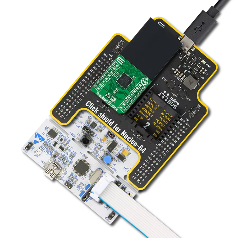
Click Shield for Nucleo-32 is the perfect way to expand your development board's functionalities with STM32 Nucleo-32 pinout. The Click Shield for Nucleo-32 provides two mikroBUS™ sockets to add any functionality from our ever-growing range of Click boards™. We are fully stocked with everything, from sensors and WiFi transceivers to motor control and audio amplifiers. The Click Shield for Nucleo-32 is compatible with the STM32 Nucleo-32 board, providing an affordable and flexible way for users to try out new ideas and quickly create prototypes with any STM32 microcontrollers, choosing from the various combinations of performance, power consumption, and features. The STM32 Nucleo-32 boards do not require any separate probe as they integrate the ST-LINK/V2-1 debugger/programmer and come with the STM32 comprehensive software HAL library and various packaged software examples. This development platform provides users with an effortless and common way to combine the STM32 Nucleo-32 footprint compatible board with their favorite Click boards™ in their upcoming projects.

Used MCU Pins
mikroBUS™ mapper
Take a closer look
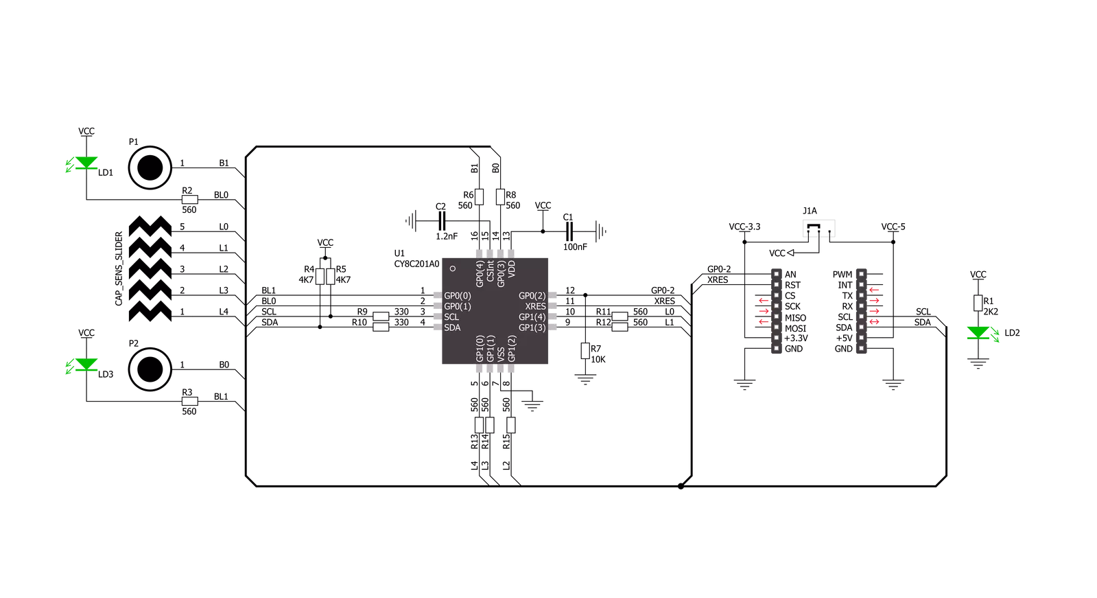
Click board™ Schematic
Step by step
Project assembly

Start by selecting your development board and Click board™. Begin with the Nucleo 32 with STM32F031K6 MCU as your development board.


Track your results in real time
Application Output
1. Application Output - In Debug mode, the 'Application Output' window enables real-time data monitoring, offering direct insight into execution results. Ensure proper data display by configuring the environment correctly using the provided tutorial.

2. UART Terminal - Use the UART Terminal to monitor data transmission via a USB to UART converter, allowing direct communication between the Click board™ and your development system. Configure the baud rate and other serial settings according to your project's requirements to ensure proper functionality. For step-by-step setup instructions, refer to the provided tutorial.

3. Plot Output - The Plot feature offers a powerful way to visualize real-time sensor data, enabling trend analysis, debugging, and comparison of multiple data points. To set it up correctly, follow the provided tutorial, which includes a step-by-step example of using the Plot feature to display Click board™ readings. To use the Plot feature in your code, use the function: plot(*insert_graph_name*, variable_name);. This is a general format, and it is up to the user to replace 'insert_graph_name' with the actual graph name and 'variable_name' with the parameter to be displayed.

Software Support
Library Description
This library contains API for CapSense Click driver.
Key functions:
capsense_get_slider_lvl- This function gets slider levelcapsense_read_data- Read one byte from register addresscapsense_write_data- Generic write data function
Open Source
Code example
The complete application code and a ready-to-use project are available through the NECTO Studio Package Manager for direct installation in the NECTO Studio. The application code can also be found on the MIKROE GitHub account.
/*!
 * \file
 * \brief CapSense Click example
 *
 * # Description
 * This demo example shows level of the slider on the terminal.
 *
 * The demo application is composed of two sections :
 *
 * ## Application Init
 * Initializes device.
 *
 * ## Application Task
 * Waits user to press top and bottom button to turn Click's LEDs ON or OFF.
 * User can swipe slider to send log to the UART where one can track their changes.
 *
 *
 * \author MikroE Team
 *
 */
// ------------------------------------------------------------------- INCLUDES

#include "board.h"
#include "log.h"
#include "capsense.h"

// ------------------------------------------------------------------ VARIABLES

static capsense_t capsense;
static log_t logger;

// ------------------------------------------------------- ADDITIONAL FUNCTIONS

void bits_to_str( uint8_t num, uint8_t *s )
{
    uint8_t mask = 0x80;
    while ( mask )
    {
        if ( num & mask )
        {
            *s++ = '1';
        }
        else
        {
            *s++ = '0';
        }
        mask >>= 1;
    }
    *s = '\0';
}

// ------------------------------------------------------ APPLICATION FUNCTIONS

void application_init ( void )
{
    log_cfg_t log_cfg;
    capsense_cfg_t cfg;

    /**
     * Logger initialization.
     * Default baud rate: 115200
     * Default log level: LOG_LEVEL_DEBUG
     * @note If USB_UART_RX and USB_UART_TX
     * are defined as HAL_PIN_NC, you will
     * need to define them manually for log to work.
     * See @b LOG_MAP_USB_UART macro definition for detailed explanation.
     */
    LOG_MAP_USB_UART( log_cfg );
    log_init( &logger, &log_cfg );
    log_info( &logger, "---- Application Init ----" );

    //  Click initialization.
    capsense_cfg_setup( &cfg );
    CAPSENSE_MAP_MIKROBUS( cfg, MIKROBUS_1 );
    capsense_init( &capsense, &cfg );

    if ( CAPSENSE_ERROR == capsense_default_cfg ( &capsense ) )
    {
        log_error( &logger, " Default configuration." );
        for ( ; ; );
    }

    log_info( &logger, " Application Task " );
}

void application_task ( void )
{
    static uint8_t current_led_state = 0;
    uint8_t output_lvl[ 10 ] = { 0 };
    uint8_t button_select = 0;
    uint8_t slider_lvl = 0;
    capsense_read_data( &capsense, CAPSENSE_CS_READ_STATUS0, &button_select );
    capsense_get_slider_lvl( &capsense, &slider_lvl );
    capsense_write_data( &capsense, CAPSENSE_OUTPUT_PORT0, current_led_state );
    Delay_ms ( 100 );

    if ( 8 == button_select )
    {
        current_led_state ^= 0x01;
        log_printf( &logger, "Toggle LED1\r\n");
        Delay_ms ( 100 );
    }
    if ( 16 == button_select )
    {
        current_led_state ^= 0x02;
        log_printf( &logger, "Toggle LED2\r\n");
        Delay_ms ( 100 );
    }
    if ( 24 == button_select )
    {
        current_led_state = ~current_led_state;
        log_printf( &logger, "Toggle both LEDs\r\n");
        Delay_ms ( 100 );
    }

    if ( slider_lvl )
    {
        bits_to_str( slider_lvl, output_lvl );
        log_printf( &logger, "Slider level - channels [5-1]:\t%s \r\n", &output_lvl[ 3 ] );
        Delay_ms ( 100 );
    }
}

int main ( void )
{
    /* Do not remove this line or clock might not be set correctly. */
    #ifdef PREINIT_SUPPORTED
    preinit();
    #endif

    application_init( );

    for ( ; ; )
    {
        application_task( );
    }

    return 0;
}


// ------------------------------------------------------------------------ END
Additional Support
Resources
Category:Capacitive