Create a safe environment by continuously monitoring CO levels with MQ-7 and STM32F031K6
Guardian against the silent enemy
Published Oct 01, 2024
Click board™
CO Click
Dev. board
Nucleo 32 with STM32F031K6 MCU
Compiler
NECTO Studio
MCU
STM32F031K6
Ready to take action against carbon monoxide? Here is the solution.
A
A
Hardware Overview
How does it work?
CO Click is based on the MQ-7, a carbon monoxide sensor from Zhengzhou Winsen Electronics Technology, which detects carbon monoxide's presence and concentration in the air. The gas sensing layer on the MQ-7 sensor unit is made of Tin dioxide (SnO2), which has lower conductivity in clean air. The conductivity increases as the levels of carbon monoxide rise. It has a high sensitivity to carbon monoxide in a wide range suitable for detecting carbon monoxide in concentrations from
20 to 2000ppm. Besides a binary indication of the presence of carbon monoxide, the MQ-7 also provides an analog representation of its concentration in the air sent directly to an analog pin of the mikroBUS™ socket labeled OUT. The sensor's analog output voltage varies in proportion to the carbon monoxide concentration; the higher the carbon monoxide concentration in the air, the higher the output voltage. Also, the MQ-7 has a built-in potentiometer that allows you to adjust the
Load Resistance of the sensor circuit. This Click board™ can be operated only with a 5V logic voltage level. The board must perform appropriate logic voltage level conversion before using MCUs with different logic levels. However, the Click board™ comes equipped with a library containing functions and an example code that can be used, as a reference, for further development.

Features overview
Development board
Nucleo 32 with STM32F031K6 MCU board provides an affordable and flexible platform for experimenting with STM32 microcontrollers in 32-pin packages. Featuring Arduino™ Nano connectivity, it allows easy expansion with specialized shields, while being mbed-enabled for seamless integration with online resources. The
board includes an on-board ST-LINK/V2-1 debugger/programmer, supporting USB reenumeration with three interfaces: Virtual Com port, mass storage, and debug port. It offers a flexible power supply through either USB VBUS or an external source. Additionally, it includes three LEDs (LD1 for USB communication, LD2 for power,
and LD3 as a user LED) and a reset push button. The STM32 Nucleo-32 board is supported by various Integrated Development Environments (IDEs) such as IAR™, Keil®, and GCC-based IDEs like AC6 SW4STM32, making it a versatile tool for developers.

Microcontroller Overview
MCU Card / MCU

Architecture
ARM Cortex-M0
MCU Memory (KB)
32
Silicon Vendor
STMicroelectronics
Pin count
32
RAM (Bytes)
4096
You complete me!
Accessories
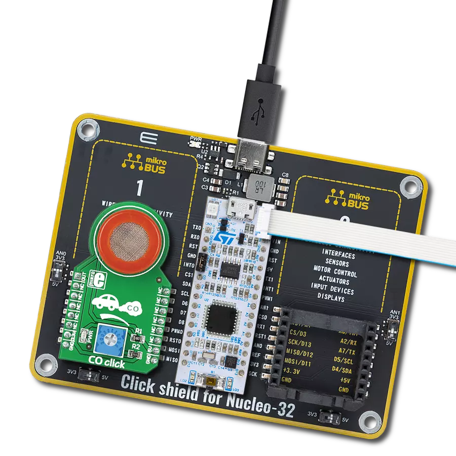
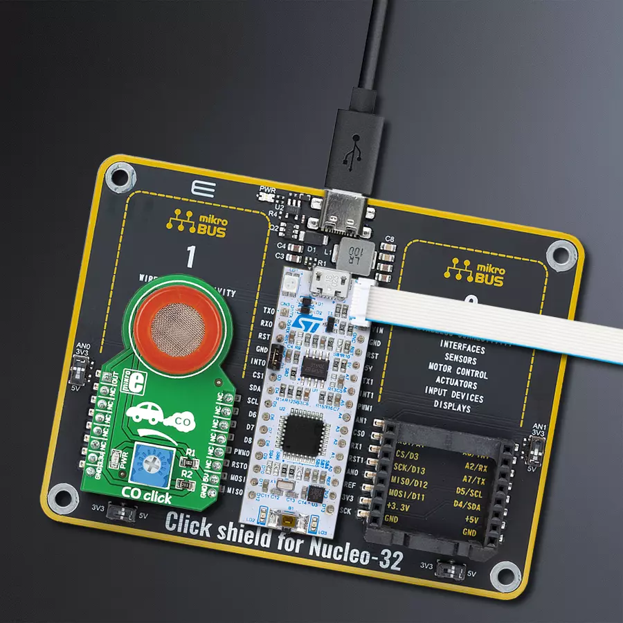
Click Shield for Nucleo-32 is the perfect way to expand your development board's functionalities with STM32 Nucleo-32 pinout. The Click Shield for Nucleo-32 provides two mikroBUS™ sockets to add any functionality from our ever-growing range of Click boards™. We are fully stocked with everything, from sensors and WiFi transceivers to motor control and audio amplifiers. The Click Shield for Nucleo-32 is compatible with the STM32 Nucleo-32 board, providing an affordable and flexible way for users to try out new ideas and quickly create prototypes with any STM32 microcontrollers, choosing from the various combinations of performance, power consumption, and features. The STM32 Nucleo-32 boards do not require any separate probe as they integrate the ST-LINK/V2-1 debugger/programmer and come with the STM32 comprehensive software HAL library and various packaged software examples. This development platform provides users with an effortless and common way to combine the STM32 Nucleo-32 footprint compatible board with their favorite Click boards™ in their upcoming projects.

Used MCU Pins
mikroBUS™ mapper
Take a closer look
Click board™ Schematic

Step by step
Project assembly

Start by selecting your development board and Click board™. Begin with the Nucleo 32 with STM32F031K6 MCU as your development board.


Software Support
Library Description
This library contains API for CO Click driver.
Key functions:
co_read_an_pin_value- This function reads results of AD conversion of the AN pin.co_read_an_pin_voltage- This function reads results of AD conversion of the AN pin and converts them to proportional voltage level.
Open Source
Code example
The complete application code and a ready-to-use project are available through the NECTO Studio Package Manager for direct installation in the NECTO Studio. The application code can also be found on the MIKROE GitHub account.
/*!
 * @file main.c
 * @brief CO Click Example.
 *
 * # Description
 * The demo application shows the reading of the adc
 * values given by the sensors.
 *
 * The demo application is composed of two sections :
 *
 * ## Application Init
 * Configuring Clicks and log objects.
 *
 * ## Application Task
 * Reads the adc value and prints in two forms (DEC and HEX).
 *
 * @author Jelena Milosavljevic
 *
 */

#include "board.h"
#include "log.h"
#include "co.h"

static co_t co;   /**< CO Click driver object. */
static log_t logger;    /**< Logger object. */

void application_init ( void ) {
    log_cfg_t log_cfg;  /**< Logger config object. */
    co_cfg_t co_cfg;  /**< Click config object. */

    /**
     * Logger initialization.
     * Default baud rate: 115200
     * Default log level: LOG_LEVEL_DEBUG
     * @note If USB_UART_RX and USB_UART_TX
     * are defined as HAL_PIN_NC, you will
     * need to define them manually for log to work.
     * See @b LOG_MAP_USB_UART macro definition for detailed explanation.
     */
    LOG_MAP_USB_UART( log_cfg );
    log_init( &logger, &log_cfg );
    log_info( &logger, " Application Init " );

    // Click initialization.

    co_cfg_setup( &co_cfg );
    CO_MAP_MIKROBUS( co_cfg, MIKROBUS_1 );
    if ( co_init( &co, &co_cfg ) == ADC_ERROR ) {
        log_error( &logger, " Application Init Error. " );
        log_info( &logger, " Please, run program again... " );

        for ( ; ; );
    }
    log_info( &logger, " Application Task " );
    Delay_ms ( 100 );
}

void application_task ( void ) {
    uint16_t co_an_value = 0;

    if ( co_read_an_pin_value ( &co, &co_an_value ) != ADC_ERROR ) {
        log_printf( &logger, " ADC Value : %u\r\n", co_an_value );
    }

    float co_an_voltage = 0;

    if ( co_read_an_pin_voltage ( &co, &co_an_voltage ) != ADC_ERROR ) {
        log_printf( &logger, " AN Voltage : %.3f[V]\r\n\n", co_an_voltage );
    }

    Delay_ms ( 1000 );
}

int main ( void )
{
    /* Do not remove this line or clock might not be set correctly. */
    #ifdef PREINIT_SUPPORTED
    preinit();
    #endif

    application_init( );

    for ( ; ; )
    {
        application_task( );
    }

    return 0;
}

// ------------------------------------------------------------------------ END
Additional Support
Resources
Category:Gas


