Convert digital signals into precise analog voltage outputs using the DAC7558 and STM32F031K6
12-bit octal-channel voltage-output digital-to-analog (DAC)

Published Oct 01, 2024
Click board™
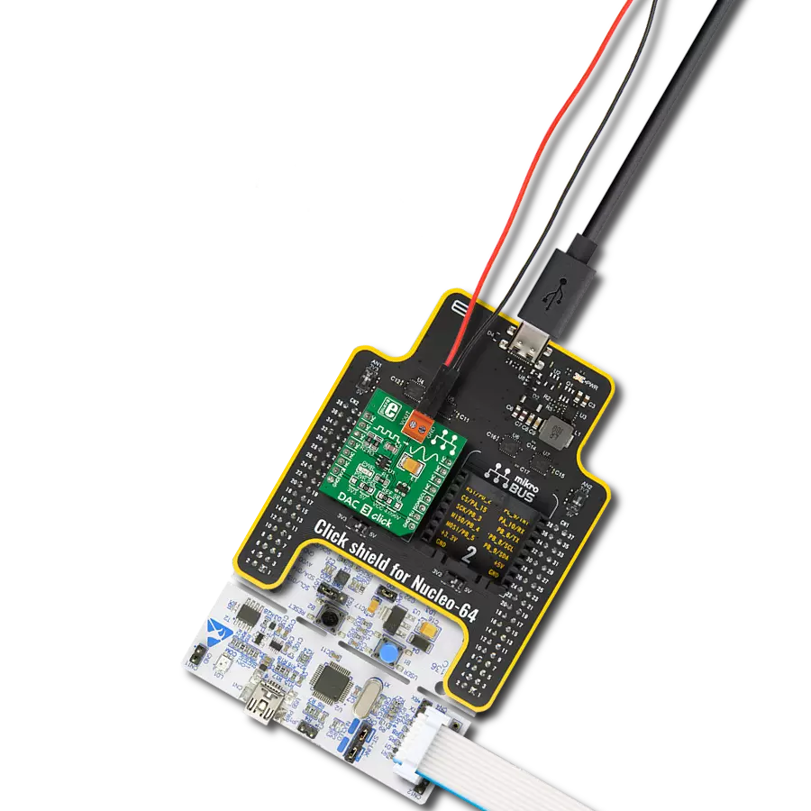
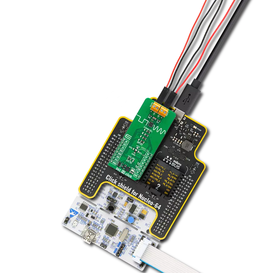
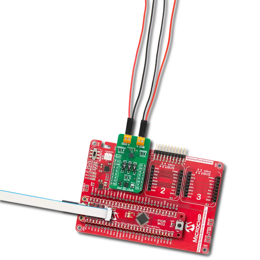
DAC 17 Click
Dev. board
Nucleo 32 with STM32F031K6 MCU
Compiler
NECTO Studio
MCU
STM32F031K6
Precise voltage output control for applications like digital gain adjustment, programmable voltage sources, and industrial process control.
A
A
Hardware Overview
How does it work?
DAC 17 Click is based on the DAC7558, a 12-bit, octal-channel voltage output DAC from Texas Instruments, known for its exceptional linearity and monotonicity. Its proprietary architecture mitigates undesired transients, such as code-to-code glitches and channel-to-channel crosstalk. Operating within a voltage range of 2.7V to 5.5V, the DAC7558 offers versatility. The board provides the flexibility of powering the IC internally or externally by setting the VCC SEL jumper to either the VIO or VEXT position. The VIO option enables internal powering of the Click board™, providing a choice between 3.3V or 5V. On the other hand, the VEXT option allows users to externally supply power in the range of 2.7 to 5.5V (applied to VEXT pins), offering flexibility in power supply according to specific system requirements. Featuring output amplifiers capable of driving a 2Ω, 200pF load rail-to-rail with a rapid settling time of 5µs, the
DAC7558 ensures precise and efficient performance. Users can configure the output range of DAC channels (from CHA to CHH) by connecting an external voltage reference to one of the REFx terminals in a range from 0V to a value of the main IC supply, VCC. Additionally, the board offers a selection between internal and external voltage reference sources. This selection is made via the VREF SEL jumpers, allowing users to choose between internal or external voltage reference options. The DAC7558 offers versatility in operation, with the ability to update outputs simultaneously or sequentially. Its integrated Power-on-Reset circuit guarantees that DAC outputs power up to zero volts during initialization. Furthermore, a Power-Down feature, controllable via the PD pin of the mikroBUS™ socket, reduces the device's current consumption to under 2µA, enhancing efficiency and prolonging battery life.
Communication with the host MCU is achieved through the 4-wire SPI serial interface, supporting clock rates of up to 50MHz. This interface is compatible with SPI, QSPI, Microwire™, and DSP standards, ensuring easy integration into various systems. The DAC7558 also uses an active-low reset feature via the RST pin on the mikroBUS™ socket. When the RST pin is set to a LOW logic state, all DAC channels are reset to zero scale. This Click board™ can operate with either 3.3V or 5V logic voltage levels selected via the VIO SEL jumper. This way, both 3.3V and 5V capable MCUs can use the communication lines properly. Also, this Click board™ comes equipped with a library containing easy-to-use functions and an example code that can be used as a reference for further development.

Features overview
Development board
Nucleo 32 with STM32F031K6 MCU board provides an affordable and flexible platform for experimenting with STM32 microcontrollers in 32-pin packages. Featuring Arduino™ Nano connectivity, it allows easy expansion with specialized shields, while being mbed-enabled for seamless integration with online resources. The
board includes an on-board ST-LINK/V2-1 debugger/programmer, supporting USB reenumeration with three interfaces: Virtual Com port, mass storage, and debug port. It offers a flexible power supply through either USB VBUS or an external source. Additionally, it includes three LEDs (LD1 for USB communication, LD2 for power,
and LD3 as a user LED) and a reset push button. The STM32 Nucleo-32 board is supported by various Integrated Development Environments (IDEs) such as IAR™, Keil®, and GCC-based IDEs like AC6 SW4STM32, making it a versatile tool for developers.

Microcontroller Overview
MCU Card / MCU

Architecture
ARM Cortex-M0
MCU Memory (KB)
32
Silicon Vendor
STMicroelectronics
Pin count
32
RAM (Bytes)
4096
You complete me!
Accessories
Click Shield for Nucleo-32 is the perfect way to expand your development board's functionalities with STM32 Nucleo-32 pinout. The Click Shield for Nucleo-32 provides two mikroBUS™ sockets to add any functionality from our ever-growing range of Click boards™. We are fully stocked with everything, from sensors and WiFi transceivers to motor control and audio amplifiers. The Click Shield for Nucleo-32 is compatible with the STM32 Nucleo-32 board, providing an affordable and flexible way for users to try out new ideas and quickly create prototypes with any STM32 microcontrollers, choosing from the various combinations of performance, power consumption, and features. The STM32 Nucleo-32 boards do not require any separate probe as they integrate the ST-LINK/V2-1 debugger/programmer and come with the STM32 comprehensive software HAL library and various packaged software examples. This development platform provides users with an effortless and common way to combine the STM32 Nucleo-32 footprint compatible board with their favorite Click boards™ in their upcoming projects.

Used MCU Pins
mikroBUS™ mapper
Take a closer look
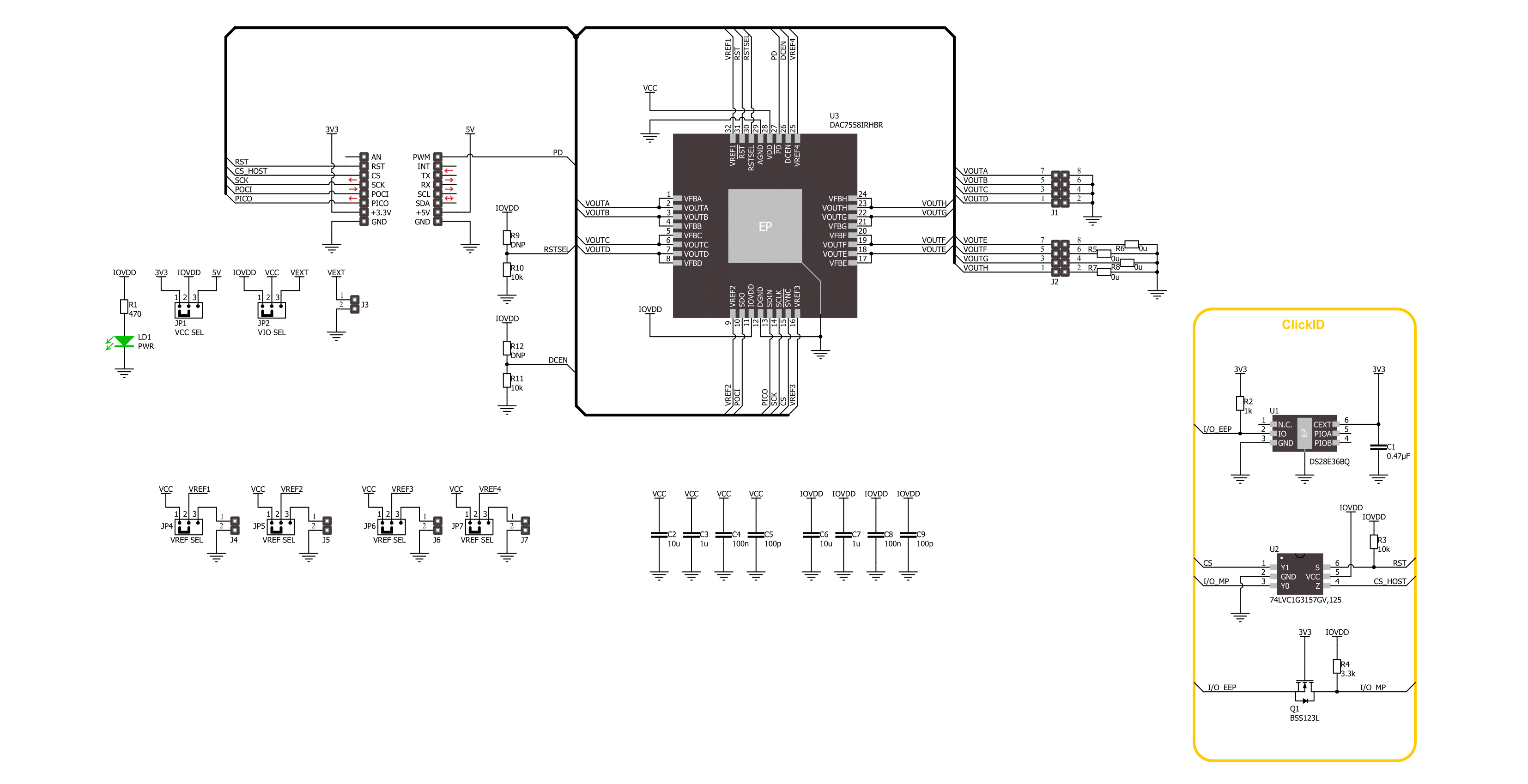
Click board™ Schematic
Step by step
Project assembly

Start by selecting your development board and Click board™. Begin with the Nucleo 32 with STM32F031K6 MCU as your development board.


Track your results in real time
Application Output
1. Application Output - In Debug mode, the 'Application Output' window enables real-time data monitoring, offering direct insight into execution results. Ensure proper data display by configuring the environment correctly using the provided tutorial.

2. UART Terminal - Use the UART Terminal to monitor data transmission via a USB to UART converter, allowing direct communication between the Click board™ and your development system. Configure the baud rate and other serial settings according to your project's requirements to ensure proper functionality. For step-by-step setup instructions, refer to the provided tutorial.

3. Plot Output - The Plot feature offers a powerful way to visualize real-time sensor data, enabling trend analysis, debugging, and comparison of multiple data points. To set it up correctly, follow the provided tutorial, which includes a step-by-step example of using the Plot feature to display Click board™ readings. To use the Plot feature in your code, use the function: plot(*insert_graph_name*, variable_name);. This is a general format, and it is up to the user to replace 'insert_graph_name' with the actual graph name and 'variable_name' with the parameter to be displayed.

Software Support
Library Description
This library contains API for DAC 17Click driver.
Key functions:
dac17_send_command- This function is used to send specific command of the DAC 17 click board.dac17_set_dac_output- This function is used to set output level of the sellected channel of the DAC 17 click board.dac17_set_all_dac_output- This function is used to set output level of the DAC 17 click board.
Open Source
Code example
The complete application code and a ready-to-use project are available through the NECTO Studio Package Manager for direct installation in the NECTO Studio. The application code can also be found on the MIKROE GitHub account.
/*!
 * @file main.c
 * @brief DAC 17 Click example
 *
 * # Description
 * This example demonstrates the use of DAC 17 Click board
 * by changing the voltage level on the output channels.
 *
 * The demo application is composed of two sections :
 *
 * ## Application Init
 * Initializes the driver and performs Click default configuration.
 *
 * ## Application Task
 * Changes the output channels voltage level starting from full scale ( REF voltage ),
 * to the mid-scale ( half of the REF voltage ), and then to zero every two seconds.
 *
 * @author Stefan Ilic
 *
 */

#include "board.h"
#include "log.h"
#include "dac17.h"

static dac17_t dac17;
static log_t logger;

void application_init ( void )
{
    log_cfg_t log_cfg;  /**< Logger config object. */
    dac17_cfg_t dac17_cfg;  /**< Click config object. */

    /**
     * Logger initialization.
     * Default baud rate: 115200
     * Default log level: LOG_LEVEL_DEBUG
     * @note If USB_UART_RX and USB_UART_TX
     * are defined as HAL_PIN_NC, you will
     * need to define them manually for log to work.
     * See @b LOG_MAP_USB_UART macro definition for detailed explanation.
     */
    LOG_MAP_USB_UART( log_cfg );
    log_init( &logger, &log_cfg );
    log_info( &logger, " Application Init " );

    // Click initialization.
    dac17_cfg_setup( &dac17_cfg );
    DAC17_MAP_MIKROBUS( dac17_cfg, MIKROBUS_1 );
    if ( SPI_MASTER_ERROR == dac17_init( &dac17, &dac17_cfg ) )
    {
        log_error( &logger, " Communication init." );
        for ( ; ; );
    }

    if ( DAC17_ERROR == dac17_default_cfg ( &dac17 ) )
    {
        log_error( &logger, " Default configuration." );
        for ( ; ; );
    }

    log_info( &logger, " Application Task " );
}

void application_task ( void )
{
    #define DAC17_OUTPUT_ZERO           0x0000u
    #define DAC17_OUTPUT_MID_SCALE      0x0800u
    #define DAC17_OUTPUT_FULL_SCALE     0x0FFFu

    log_printf( &logger, " Setting all channels to full scale output \r\n" );
    dac17_set_all_dac_output( &dac17, DAC17_OUTPUT_FULL_SCALE );
    Delay_ms ( 1000 );
    Delay_ms ( 1000 );

    log_printf( &logger, " Setting all channels outputs to zero \r\n" );
    dac17_set_all_dac_output( &dac17, DAC17_OUTPUT_ZERO );
    Delay_ms ( 1000 );
    Delay_ms ( 1000 );

    log_printf( &logger, " Setting all channels outputs to mid scale \r\n" );
    dac17_set_all_dac_output( &dac17, DAC17_OUTPUT_MID_SCALE );
    Delay_ms ( 1000 );
    Delay_ms ( 1000 );
}

int main ( void )
{
    /* Do not remove this line or clock might not be set correctly. */
    #ifdef PREINIT_SUPPORTED
    preinit();
    #endif

    application_init( );

    for ( ; ; )
    {
        application_task( );
    }

    return 0;
}

// ------------------------------------------------------------------------ END
Additional Support
Resources
Category:DAC