Save calibration data and system logs with M95P32-I and STM32F031K6
Infinite ideas, instant recall

Published Oct 01, 2024
Click board™
EEPROM 9 Click
Dev. board
Nucleo 32 with STM32F031K6 MCU
Compiler
NECTO Studio
MCU
STM32F031K6
Our EEPROM solution guarantees secure data storage, which is ideal for sensitive information such as encryption keys, boot sequences, and critical system parameters
A
A
Hardware Overview
How does it work?
EEPROM 9 Click is based on the M95P32-I, a 32Mbit SPI page EEPROM device from STMicroelectronics, divided into 8192 erasable pages of 512 bytes (organized either as 1024 erasable sectors of 4 Kbytes, 64 erasable blocks of 64 Kbytes or as an entirely erasable array). The M95P32-I is manufactured with ST's advanced proprietary NVM technology and offers byte flexibility, page alterability, high page cycling performance, and ultra-low power consumption. It is highly reliable, lasting 500k write cycles with 100 years of data retention (10 years after 500k cycles), which makes it suitable for various applications where dependable nonvolatile memory storage is essential. This Click board™ communicates with MCU using the SPI serial interface that supports the two most common modes, SPI Mode 0 and 3, with a maximum SPI frequency of 80MHz.
As mentioned, the M95P32-I offers byte and page write instructions of up to 512 bytes. Write instructions consist of self-timed auto-erase and program operations, resulting in flexible data byte management. It also accepts page/block/sector/chip erase commands to set the memory to an erased state. The memory can then be fast-programmed by pages of 512 bytes and further optimized using the "page program with buffer load" to hide the SPI communication latency. Additional status, configuration, and volatile registers set the desired device configuration, while the safety register gives device status information. In addition to the SPI communication, the EEPROM 9 Click has two additional pins used for Write Protection and Communication Hold function routed to the WP and HLD pins of the mikroBUS™ socket.
The HLD pin of the mikroBUS™ socket can be used to pause the serial communication with the M95P32-I without deselecting the device. The configurable Write Protection function routed to the WP pin of the mikroBUS™ socket allows the user to freeze the memory area protected against Write instructions in a read-only mode (as specified by the values in the BPx and TB bits of the STATUS register). This Click board™ can be operated only with a 3.3V logic voltage level. The board must perform appropriate logic voltage level conversion before using MCUs with different logic levels. Also, it comes equipped with a library containing functions and an example code that can be used, as a reference, for further development.


Features overview
Development board
Nucleo 32 with STM32F031K6 MCU board provides an affordable and flexible platform for experimenting with STM32 microcontrollers in 32-pin packages. Featuring Arduino™ Nano connectivity, it allows easy expansion with specialized shields, while being mbed-enabled for seamless integration with online resources. The
board includes an on-board ST-LINK/V2-1 debugger/programmer, supporting USB reenumeration with three interfaces: Virtual Com port, mass storage, and debug port. It offers a flexible power supply through either USB VBUS or an external source. Additionally, it includes three LEDs (LD1 for USB communication, LD2 for power,
and LD3 as a user LED) and a reset push button. The STM32 Nucleo-32 board is supported by various Integrated Development Environments (IDEs) such as IAR™, Keil®, and GCC-based IDEs like AC6 SW4STM32, making it a versatile tool for developers.

Microcontroller Overview
MCU Card / MCU

Architecture
ARM Cortex-M0
MCU Memory (KB)
32
Silicon Vendor
STMicroelectronics
Pin count
32
RAM (Bytes)
4096
You complete me!
Accessories
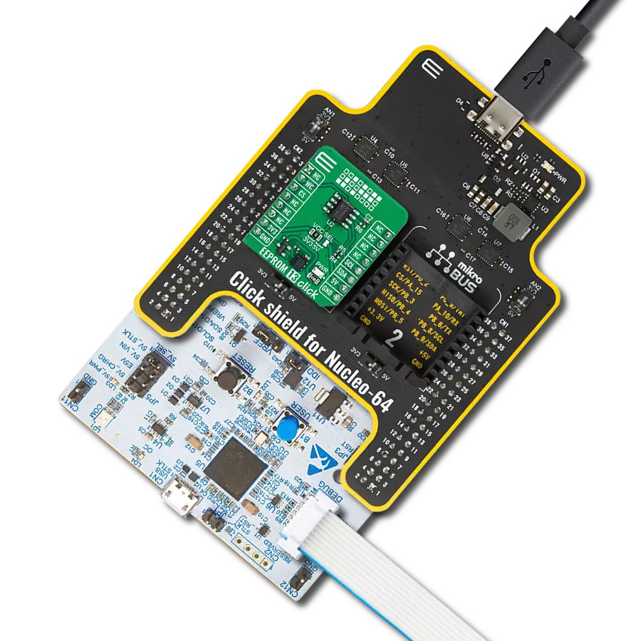
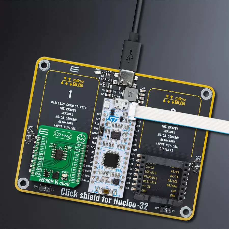
Click Shield for Nucleo-32 is the perfect way to expand your development board's functionalities with STM32 Nucleo-32 pinout. The Click Shield for Nucleo-32 provides two mikroBUS™ sockets to add any functionality from our ever-growing range of Click boards™. We are fully stocked with everything, from sensors and WiFi transceivers to motor control and audio amplifiers. The Click Shield for Nucleo-32 is compatible with the STM32 Nucleo-32 board, providing an affordable and flexible way for users to try out new ideas and quickly create prototypes with any STM32 microcontrollers, choosing from the various combinations of performance, power consumption, and features. The STM32 Nucleo-32 boards do not require any separate probe as they integrate the ST-LINK/V2-1 debugger/programmer and come with the STM32 comprehensive software HAL library and various packaged software examples. This development platform provides users with an effortless and common way to combine the STM32 Nucleo-32 footprint compatible board with their favorite Click boards™ in their upcoming projects.

Used MCU Pins
mikroBUS™ mapper
Take a closer look
Click board™ Schematic

Step by step
Project assembly

Start by selecting your development board and Click board™. Begin with the Nucleo 32 with STM32F031K6 MCU as your development board.


Track your results in real time
Application Output
1. Application Output - In Debug mode, the 'Application Output' window enables real-time data monitoring, offering direct insight into execution results. Ensure proper data display by configuring the environment correctly using the provided tutorial.

2. UART Terminal - Use the UART Terminal to monitor data transmission via a USB to UART converter, allowing direct communication between the Click board™ and your development system. Configure the baud rate and other serial settings according to your project's requirements to ensure proper functionality. For step-by-step setup instructions, refer to the provided tutorial.

3. Plot Output - The Plot feature offers a powerful way to visualize real-time sensor data, enabling trend analysis, debugging, and comparison of multiple data points. To set it up correctly, follow the provided tutorial, which includes a step-by-step example of using the Plot feature to display Click board™ readings. To use the Plot feature in your code, use the function: plot(*insert_graph_name*, variable_name);. This is a general format, and it is up to the user to replace 'insert_graph_name' with the actual graph name and 'variable_name' with the parameter to be displayed.

Software Support
Library Description
This library contains API for EEPROM 9 Click driver.
Key functions:
eeprom9_set_write_enable- EEPROM 9 enable write functioneeprom9_read_memory- EEPROM 9 memory reading functioneeprom9_block_erase- EEPROM 9 memory block erase function.
Open Source
Code example
The complete application code and a ready-to-use project are available through the NECTO Studio Package Manager for direct installation in the NECTO Studio. The application code can also be found on the MIKROE GitHub account.
/*!
 * @file main.c
 * @brief EEPROM 9 Click example
 *
 * # Description
 * This is an example that demonstrates the use of the EEPROM 9 Click board.
 *
 * The demo application is composed of two sections :
 *
 * ## Application Init
 * Initializes the driver and USB UART logging, disables hold and write protection.
 *
 * ## Application Task
 * Writes a desired number of data bytes to the EEPROM 9 memory into a specified address,
 * and verifies that it is written correctly by reading from the same memory location.
 *
 * @author Stefan Ilic
 *
 */

#include "board.h"
#include "log.h"
#include "eeprom9.h"

static eeprom9_t eeprom9;
static log_t logger;
static char demo_data[ 9 ] = { 'M', 'i', 'k', 'r', 'o', 'E', 13 ,10 , 0 };

#define MEMORY_ADDRESS  0x0300

void application_init ( void )
{
    log_cfg_t log_cfg;  /**< Logger config object. */
    eeprom9_cfg_t eeprom9_cfg;  /**< Click config object. */
    id_data_t id_data;

    /**
     * Logger initialization.
     * Default baud rate: 115200
     * Default log level: LOG_LEVEL_DEBUG
     * @note If USB_UART_RX and USB_UART_TX
     * are defined as HAL_PIN_NC, you will
     * need to define them manually for log to work.
     * See @b LOG_MAP_USB_UART macro definition for detailed explanation.
     */
    LOG_MAP_USB_UART( log_cfg );
    log_init( &logger, &log_cfg );
    log_info( &logger, " Application Init " );

    // Click initialization.
    eeprom9_cfg_setup( &eeprom9_cfg );
    EEPROM9_MAP_MIKROBUS( eeprom9_cfg, MIKROBUS_1 );
    if ( SPI_MASTER_ERROR == eeprom9_init( &eeprom9, &eeprom9_cfg ) )
    {
        log_error( &logger, " Communication init." );
        for ( ; ; );
    }

    eeprom9_read_identification( &eeprom9, &id_data );
    if ( EEPROM9_ST_MANUFACTURER_CODE != id_data.manufact_code )
    {
        log_error( &logger, " Communication error." );
        for ( ; ; );
    }
    log_printf( &logger, " Manufacturer code: 0x%.2X \r\n", ( uint16_t ) id_data.manufact_code );

    log_printf( &logger, " Disabling Hold \r\n" );
    eeprom9_set_hold( &eeprom9, EEPROM9_HOLD_DISABLE );
    Delay_ms ( 100 );

    log_printf( &logger, " Disabling Write Protection \r\n" );
    eeprom9_set_write_protection( &eeprom9, EEPROM9_WRITE_PROTECT_DISABLE );
    Delay_ms ( 100 );

    log_info( &logger, " Application Task " );
    log_printf( &logger, " - - - - - - - - - - - \r\n" );
}

void application_task ( void )
{
    char rx_data[ 9 ] = { 0 };

    eeprom9_set_write_enable( &eeprom9, EEPROM9_WRITE_ENABLE );
    Delay_ms ( 10 );

    eeprom9_write_memory( &eeprom9, MEMORY_ADDRESS, demo_data, 9 );
    log_printf( &logger, " Write data: %s", demo_data );
    Delay_ms ( 100 );

    eeprom9_read_memory( &eeprom9, MEMORY_ADDRESS, rx_data, 9 );
    log_printf( &logger, " Read data: %s", rx_data );
    log_printf( &logger, " - - - - - - - - - - - \r\n" );

    Delay_ms ( 1000 );

}

int main ( void )
{
    /* Do not remove this line or clock might not be set correctly. */
    #ifdef PREINIT_SUPPORTED
    preinit();
    #endif

    application_init( );

    for ( ; ; )
    {
        application_task( );
    }

    return 0;
}

// ------------------------------------------------------------------------ END
Additional Support
Resources
Category:EEPROM