Optimize DC load management for efficiency with G6D-ASI and STM32F031K6
Say goodbye to clicks and clacks

Published Oct 01, 2024
Click board™
FLICKER Click
Dev. board
Nucleo 32 with STM32F031K6 MCU
Compiler
NECTO Studio
MCU
STM32F031K6
Switch to a world of convenience and reliability with our power PCB relay – the smart choice for your electrical control needs
A
A
Hardware Overview
How does it work?
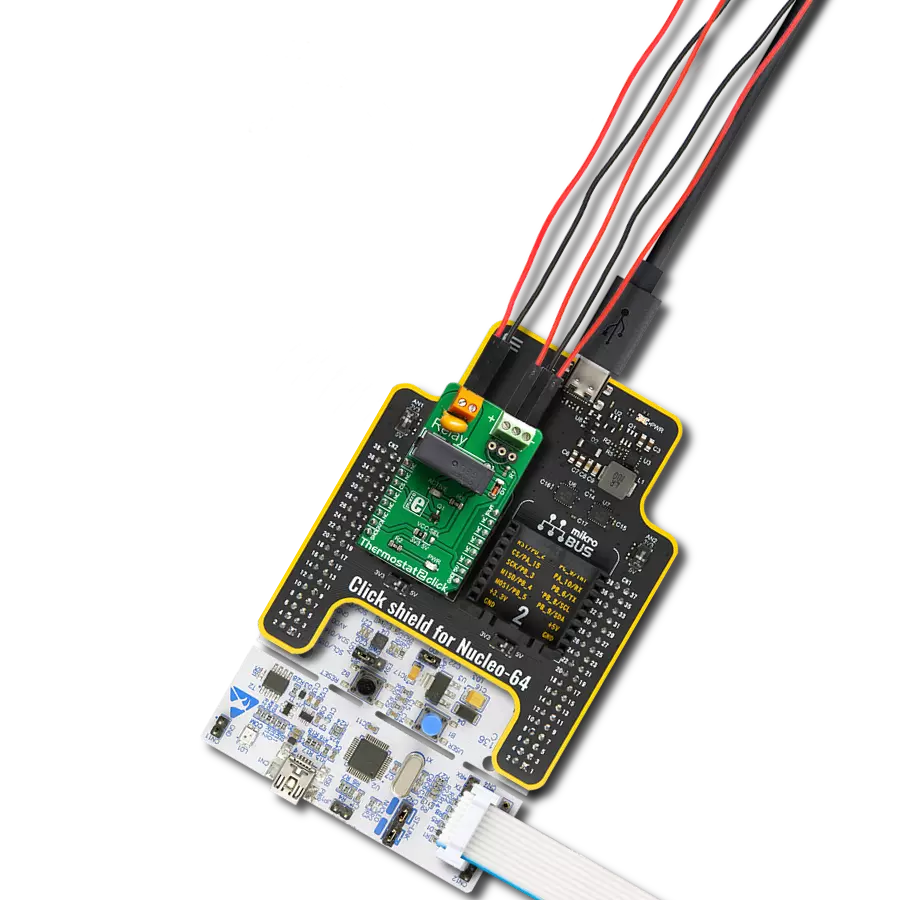
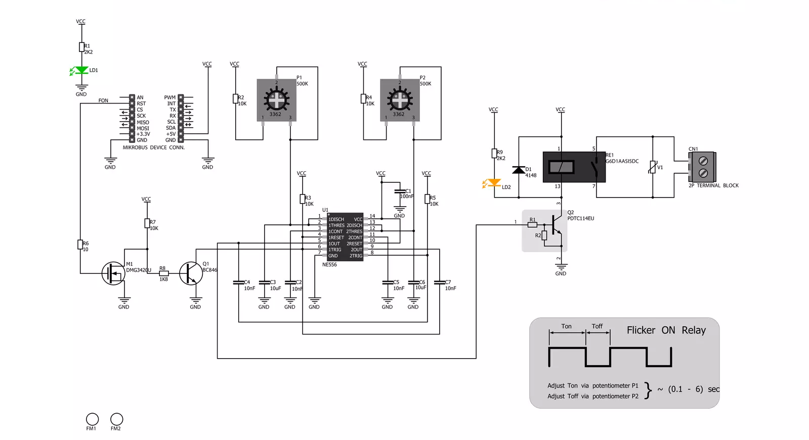
Flicker Click is based on the G6D-ASI, a power PCB relay from OMRON. It has a long service life with up to 300.000 operations at maximum rated loads. Its contact resistance is 100mΩ, with 5ms of release time, and it is designed to withstand 500VDC. Its coil is powered by 5V from the mikroBUS™ socket. The load can be connected to the relay over the onboard screw terminal and isolated from the board. Remember not to touch the board while the external power supply is on; the Flicker Click has exposed pins/pads. Thanks to
the onboard NE556, a dual precision timer from Texas Instruments, and two onboard 500K potentiometers, you can easily set the on/off periods. You will need a fine screwdriver to set the desired position of the potentiometers. A stopwatch can measure the ON/OFF periods if you need precise time. This way, you can set different or the same periods for both on and off states. The onboard LED stands for the visual presentation of the status of the relay. The Flicker Click uses a FON pin of the mikroBUS™ socket to communicate
with the host MCU. Over this pin, you can turn the NE556 ON and OFF. This Click board™ can be operated only with a 5V logic voltage level. The board must perform appropriate logic voltage level conversion before using MCUs with different logic levels. Also, it comes equipped with a library containing functions and an example code that can be used as a reference for further development.

Features overview
Development board
Nucleo 32 with STM32F031K6 MCU board provides an affordable and flexible platform for experimenting with STM32 microcontrollers in 32-pin packages. Featuring Arduino™ Nano connectivity, it allows easy expansion with specialized shields, while being mbed-enabled for seamless integration with online resources. The
board includes an on-board ST-LINK/V2-1 debugger/programmer, supporting USB reenumeration with three interfaces: Virtual Com port, mass storage, and debug port. It offers a flexible power supply through either USB VBUS or an external source. Additionally, it includes three LEDs (LD1 for USB communication, LD2 for power,
and LD3 as a user LED) and a reset push button. The STM32 Nucleo-32 board is supported by various Integrated Development Environments (IDEs) such as IAR™, Keil®, and GCC-based IDEs like AC6 SW4STM32, making it a versatile tool for developers.

Microcontroller Overview
MCU Card / MCU

Architecture
ARM Cortex-M0
MCU Memory (KB)
32
Silicon Vendor
STMicroelectronics
Pin count
32
RAM (Bytes)
4096
You complete me!
Accessories
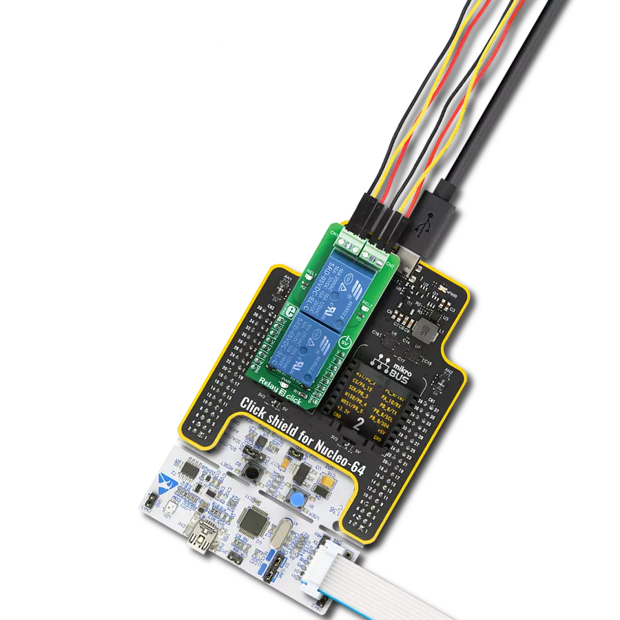
Click Shield for Nucleo-32 is the perfect way to expand your development board's functionalities with STM32 Nucleo-32 pinout. The Click Shield for Nucleo-32 provides two mikroBUS™ sockets to add any functionality from our ever-growing range of Click boards™. We are fully stocked with everything, from sensors and WiFi transceivers to motor control and audio amplifiers. The Click Shield for Nucleo-32 is compatible with the STM32 Nucleo-32 board, providing an affordable and flexible way for users to try out new ideas and quickly create prototypes with any STM32 microcontrollers, choosing from the various combinations of performance, power consumption, and features. The STM32 Nucleo-32 boards do not require any separate probe as they integrate the ST-LINK/V2-1 debugger/programmer and come with the STM32 comprehensive software HAL library and various packaged software examples. This development platform provides users with an effortless and common way to combine the STM32 Nucleo-32 footprint compatible board with their favorite Click boards™ in their upcoming projects.

Used MCU Pins
mikroBUS™ mapper
Take a closer look
Click board™ Schematic
Step by step
Project assembly

Start by selecting your development board and Click board™. Begin with the Nucleo 32 with STM32F031K6 MCU as your development board.


Software Support
Library Description
This library contains API for FLICKER Click driver.
Key functions:
flicker_engage- Flicker engage function
Open Source
Code example
The complete application code and a ready-to-use project are available through the NECTO Studio Package Manager for direct installation in the NECTO Studio. The application code can also be found on the MIKROE GitHub account.
/*!
 * \file
 * \brief Flicker Click example
 *
 * # Description
 * This application simple solution if you need to turn a device on and off at specific time intervals.
 *
 * The demo application is composed of two sections :
 *
 * ## Application Init
 * Initialization driver enables GPIO and also starts write log.
 *
 * ## Application Task
 * This example demonstrates capabilities of Flicker Click board.
 *
 * \author MikroE Team
 *
 */
// ------------------------------------------------------------------- INCLUDES

#include "board.h"
#include "log.h"
#include "flicker.h"

// ------------------------------------------------------------------ VARIABLES

static flicker_t flicker;
static log_t logger;

// ------------------------------------------------------ APPLICATION FUNCTIONS

void application_init ( void )
{
    log_cfg_t log_cfg;
    flicker_cfg_t cfg;

    /**
     * Logger initialization.
     * Default baud rate: 115200
     * Default log level: LOG_LEVEL_DEBUG
     * @note If USB_UART_RX and USB_UART_TX
     * are defined as HAL_PIN_NC, you will
     * need to define them manually for log to work.
     * See @b LOG_MAP_USB_UART macro definition for detailed explanation.
     */
    LOG_MAP_USB_UART( log_cfg );
    log_init( &logger, &log_cfg );
    log_info(&logger, "---- Application Init ----");

    //  Click initialization.

    flicker_cfg_setup( &cfg );
    FLICKER_MAP_MIKROBUS( cfg, MIKROBUS_1 );
    flicker_init( &flicker, &cfg );
}

void application_task ( void )
{
    //  Task implementation.

    log_printf( &logger, " *Flicker on!* \r\n" );
    Delay_ms ( 500 );
    flicker_engage( &flicker );
}

int main ( void )
{
    /* Do not remove this line or clock might not be set correctly. */
    #ifdef PREINIT_SUPPORTED
    preinit();
    #endif

    application_init( );

    for ( ; ; )
    {
        application_task( );
    }

    return 0;
}


// ------------------------------------------------------------------------ END
Additional Support
Resources
Category:Relay