Navigate like a PRO with NEO-M9N and STM32F031K6
Find your way, anywhere, anytime
Published Oct 01, 2024
Click board™
GNSS 7 Click
Dev. board
Nucleo 32 with STM32F031K6 MCU
Compiler
NECTO Studio
MCU
STM32F031K6
Our GNSS solution stands at the forefront of location accuracy, redefining navigation as you know it. Experience unparalleled precision that transforms your journeys into seamless adventures
A
A
Hardware Overview
How does it work?
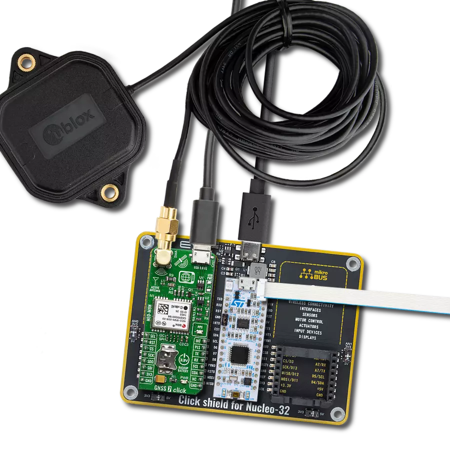
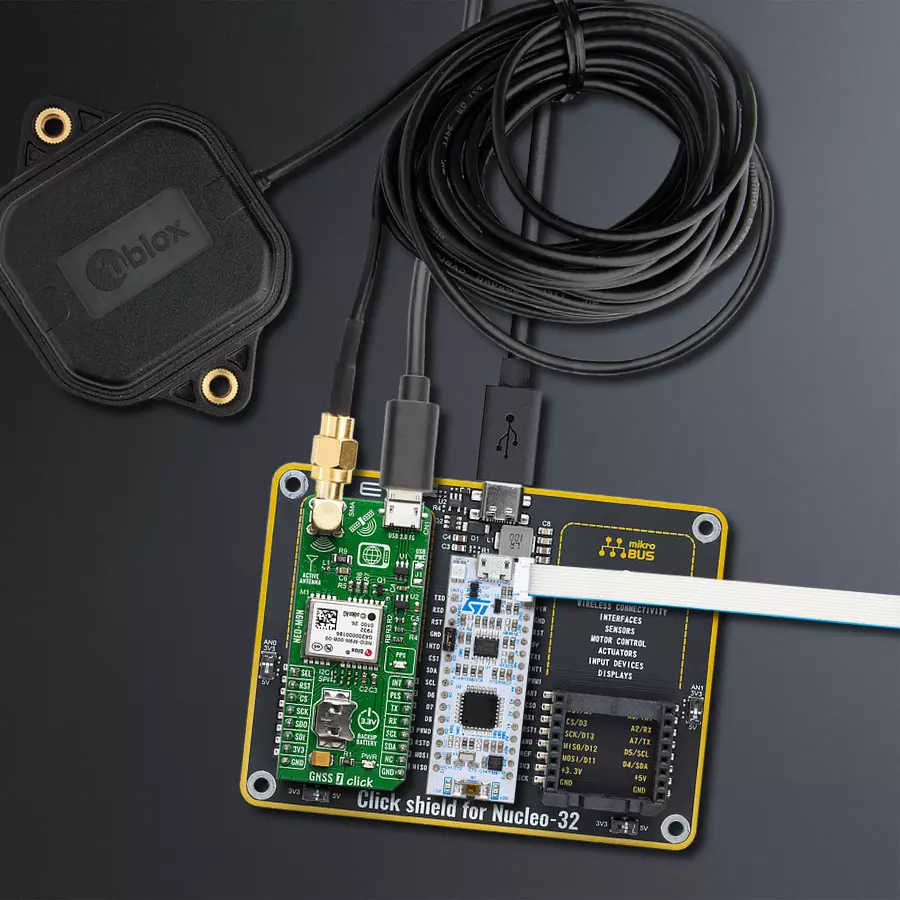
GNSS 7 Click is based on the NEO-M9N, an ultra-robust meter-level GNSS positioning receiver module from u-blox. The module features onboard serial flash memory, message integrity protection, anti-jamming, anti-spoofing, and many more, making this Click board™ meet even the most stringent requirements in versatile industrial and consumer applications, such as UAVs, vehicles, and assets tracking. For RF optimization, the NEO-M9N module features Advanced filtering algorithms that mitigate the impact of RF interference and jamming, thus enabling the product to operate as intended. NEO-M9N click is designed mainly for use with NSS/GLONASS-compatible active antennas. The NEO-M9 series utilizes concurrent reception of up to four GNSS (GPS, GLONASS, BeiDou, Galileo), simultaneously recognizes
multiple constellations, and provides outstanding positioning accuracy in scenarios involving urban canyons or weak signals. The u-blox NEO-M9 modules can also benefit from the u-blox AssistNow assistance service. The Online service provides GNNS broadcast parameters, e.g., ephemeris, almanac plus time, or rough position, to reduce the receiver’s time first to fix significantly and improve acquisition sensitivity. Hardware Backup Mode - If the main supply voltage fails and a battery is connected to V_BCKP, parts of the receiver switch off, but the RTC still runs, providing a timing reference for the receiver. This operating mode enables all relevant data to be saved in the backup RAM to allow a hot or warm start later. The GNSS 7-click supports both SPI and I2C/UART communication protocol configurations.
Therefore, this Click board™ has communication interface selection jumpers to allow the user to set whether to use SPI communication or combination. A USB interface (micro USB port), compatible with the USB version 2.0 FS (Full Speed, 12 Mbit/s), can be used for communication as an alternative to the UART. The USB port can also be used as a power supply if you need the click board™ to be a standalone device. This Click board™ can be operated only with a 3.3V logic voltage level. The board must perform appropriate logic voltage level conversion before using MCUs with different logic levels. Also, it comes equipped with a library containing functions and an example code that can be used as a reference for further development.

Features overview
Development board
Nucleo 32 with STM32F031K6 MCU board provides an affordable and flexible platform for experimenting with STM32 microcontrollers in 32-pin packages. Featuring Arduino™ Nano connectivity, it allows easy expansion with specialized shields, while being mbed-enabled for seamless integration with online resources. The
board includes an on-board ST-LINK/V2-1 debugger/programmer, supporting USB reenumeration with three interfaces: Virtual Com port, mass storage, and debug port. It offers a flexible power supply through either USB VBUS or an external source. Additionally, it includes three LEDs (LD1 for USB communication, LD2 for power,
and LD3 as a user LED) and a reset push button. The STM32 Nucleo-32 board is supported by various Integrated Development Environments (IDEs) such as IAR™, Keil®, and GCC-based IDEs like AC6 SW4STM32, making it a versatile tool for developers.

Microcontroller Overview
MCU Card / MCU

Architecture
ARM Cortex-M0
MCU Memory (KB)
32
Silicon Vendor
STMicroelectronics
Pin count
32
RAM (Bytes)
4096
You complete me!
Accessories
Click Shield for Nucleo-32 is the perfect way to expand your development board's functionalities with STM32 Nucleo-32 pinout. The Click Shield for Nucleo-32 provides two mikroBUS™ sockets to add any functionality from our ever-growing range of Click boards™. We are fully stocked with everything, from sensors and WiFi transceivers to motor control and audio amplifiers. The Click Shield for Nucleo-32 is compatible with the STM32 Nucleo-32 board, providing an affordable and flexible way for users to try out new ideas and quickly create prototypes with any STM32 microcontrollers, choosing from the various combinations of performance, power consumption, and features. The STM32 Nucleo-32 boards do not require any separate probe as they integrate the ST-LINK/V2-1 debugger/programmer and come with the STM32 comprehensive software HAL library and various packaged software examples. This development platform provides users with an effortless and common way to combine the STM32 Nucleo-32 footprint compatible board with their favorite Click boards™ in their upcoming projects.

GNSS Active External Antenna is a unique multi-band type of antenna coming from u-Blox that is the perfect selection for high precision GNSS applications, which require highly accurate location abilities such as RTK. The ANN-MB-00 is a multi-band (L1, L2/E5b/B2I) active GNSS antenna with a 5m cable and SMA connector. The antenna supports GPS, GLONASS, Galileo, and BeiDou and includes a high-performance multi-band RHCP dual-feed patch antenna element, a built-in high-gain LNA with SAW pre-filtering, and a 5 m antenna cable with SMA connector, and is waterproof.

Used MCU Pins
mikroBUS™ mapper
Take a closer look
Click board™ Schematic

Step by step
Project assembly

Start by selecting your development board and Click board™. Begin with the Nucleo 32 with STM32F031K6 MCU as your development board.


Track your results in real time
Application Output
1. Application Output - In Debug mode, the 'Application Output' window enables real-time data monitoring, offering direct insight into execution results. Ensure proper data display by configuring the environment correctly using the provided tutorial.

2. UART Terminal - Use the UART Terminal to monitor data transmission via a USB to UART converter, allowing direct communication between the Click board™ and your development system. Configure the baud rate and other serial settings according to your project's requirements to ensure proper functionality. For step-by-step setup instructions, refer to the provided tutorial.

3. Plot Output - The Plot feature offers a powerful way to visualize real-time sensor data, enabling trend analysis, debugging, and comparison of multiple data points. To set it up correctly, follow the provided tutorial, which includes a step-by-step example of using the Plot feature to display Click board™ readings. To use the Plot feature in your code, use the function: plot(*insert_graph_name*, variable_name);. This is a general format, and it is up to the user to replace 'insert_graph_name' with the actual graph name and 'variable_name' with the parameter to be displayed.

Software Support
Library Description
This library contains API for GNSS 7 Click driver.
Key functions:
gnss7_generic_read- This function reads a desired number of data bytes by using UART serial interfacegnss7_clear_ring_buffers- This function clears UART tx and rx ring buffersgnss7_parse_gngga- This function parses the GNGGA data from the read response buffer
Open Source
Code example
The complete application code and a ready-to-use project are available through the NECTO Studio Package Manager for direct installation in the NECTO Studio. The application code can also be found on the MIKROE GitHub account.
/*!
 * @file main.c
 * @brief GNSS 7 Click Example.
 *
 * # Description
 * This example demonstrates the use of GNSS 7 Click by reading and displaying
 * the GPS coordinates.
 *
 * The demo application is composed of two sections :
 *
 * ## Application Init
 * Initializes the driver and logger.
 *
 * ## Application Task
 * Reads the received data, parses the GNGGA info from it, and once it receives the position fix
 * it will start displaying the coordinates on the USB UART.
 *
 * ## Additional Function
 * - static void gnss7_clear_app_buf ( void )
 * - static err_t gnss7_process ( gnss7_t *ctx )
 * - static void gnss7_parser_application ( char *rsp )
 *
 * @author Stefan Filipovic
 *
 */

#include "board.h"
#include "log.h"
#include "gnss7.h"
#include "string.h"

#define PROCESS_BUFFER_SIZE 200

static gnss7_t gnss7;
static log_t logger;

static char app_buf[ PROCESS_BUFFER_SIZE ] = { 0 };
static int32_t app_buf_len = 0;

/**
 * @brief GNSS 7 clearing application buffer.
 * @details This function clears memory of application buffer and reset its length.
 * @return None.
 * @note None.
 */
static void gnss7_clear_app_buf ( void );

/**
 * @brief GNSS 7 data reading function.
 * @details This function reads data from device and concatenates data to application buffer.
 * @param[in] ctx : Click context object.
 * See #gnss7_t object definition for detailed explanation.
 * @return @li @c  0 - Read some data.
 *         @li @c -1 - Nothing is read.
 * See #err_t definition for detailed explanation.
 * @note None.
 */
static err_t gnss7_process ( gnss7_t *ctx );

/**
 * @brief GNSS 7 parser application function.
 * @details This function parses GNSS data and logs it on the USB UART. It clears app and ring buffers
 * after successfully parsing data.
 * @param[in] ctx : Click context object.
 * See #gnss7_t object definition for detailed explanation.
 * @param[in] rsp Response buffer.
 * @return None.
 * @note None.
 */
static void gnss7_parser_application ( gnss7_t *ctx, char *rsp );

void application_init ( void )
{
    log_cfg_t log_cfg;  /**< Logger config object. */
    gnss7_cfg_t gnss7_cfg;  /**< Click config object. */

    /**
     * Logger initialization.
     * Default baud rate: 115200
     * Default log level: LOG_LEVEL_DEBUG
     * @note If USB_UART_RX and USB_UART_TX
     * are defined as HAL_PIN_NC, you will
     * need to define them manually for log to work.
     * See @b LOG_MAP_USB_UART macro definition for detailed explanation.
     */
    LOG_MAP_USB_UART( log_cfg );
    log_init( &logger, &log_cfg );
    log_info( &logger, " Application Init " );

    // Click initialization.
    gnss7_cfg_setup( &gnss7_cfg );
    GNSS7_MAP_MIKROBUS( gnss7_cfg, MIKROBUS_1 );
    if ( UART_ERROR == gnss7_init( &gnss7, &gnss7_cfg ) )
    {
        log_error( &logger, " Communication init." );
        for ( ; ; );
    }
    log_info( &logger, " Application Task " );
}

void application_task ( void )
{
    if ( GNSS7_OK == gnss7_process( &gnss7 ) )
    {
        if ( PROCESS_BUFFER_SIZE == app_buf_len )
        {
            gnss7_parser_application( &gnss7, app_buf );
        }
    }
}

int main ( void )
{
    /* Do not remove this line or clock might not be set correctly. */
    #ifdef PREINIT_SUPPORTED
    preinit();
    #endif

    application_init( );

    for ( ; ; )
    {
        application_task( );
    }

    return 0;
}

static void gnss7_clear_app_buf ( void )
{
    memset( app_buf, 0, app_buf_len );
    app_buf_len = 0;
}

static err_t gnss7_process ( gnss7_t *ctx )
{
    char rx_buf[ PROCESS_BUFFER_SIZE ] = { 0 };
    int32_t rx_size = 0;
    rx_size = gnss7_generic_read( ctx, rx_buf, PROCESS_BUFFER_SIZE );
    if ( rx_size > 0 )
    {
        int32_t buf_cnt = app_buf_len;
        if ( ( ( app_buf_len + rx_size ) > PROCESS_BUFFER_SIZE ) && ( app_buf_len > 0 ) )
        {
            buf_cnt = PROCESS_BUFFER_SIZE - ( ( app_buf_len + rx_size ) - PROCESS_BUFFER_SIZE );
            memmove ( app_buf, &app_buf[ PROCESS_BUFFER_SIZE - buf_cnt ], buf_cnt );
        }
        for ( int32_t rx_cnt = 0; rx_cnt < rx_size; rx_cnt++ )
        {
            if ( rx_buf[ rx_cnt ] )
            {
                app_buf[ buf_cnt++ ] = rx_buf[ rx_cnt ];
                if ( app_buf_len < PROCESS_BUFFER_SIZE )
                {
                    app_buf_len++;
                }
            }
        }
        return GNSS7_OK;
    }
    return GNSS7_ERROR;
}

static void gnss7_parser_application ( gnss7_t *ctx, char *rsp )
{
    char element_buf[ 100 ] = { 0 };
    if ( GNSS7_OK == gnss7_parse_gngga( rsp, GNSS7_GNGGA_LATITUDE, element_buf ) )
    {
        static uint8_t wait_for_fix_cnt = 0;
        if ( strlen( element_buf ) > 0 )
        {
            log_printf( &logger, "\r\n Latitude: %.2s degrees, %s minutes \r\n", element_buf, &element_buf[ 2 ] );
            gnss7_parse_gngga( rsp, GNSS7_GNGGA_LONGITUDE, element_buf );
            log_printf( &logger, " Longitude: %.3s degrees, %s minutes \r\n", element_buf, &element_buf[ 3 ] );
            memset( element_buf, 0, sizeof( element_buf ) );
            gnss7_parse_gngga( rsp, GNSS7_GNGGA_ALTITUDE, element_buf );
            log_printf( &logger, " Altitude: %s m \r\n", element_buf );
            wait_for_fix_cnt = 0;
        }
        else
        {
            if ( wait_for_fix_cnt % 5 == 0 )
            {
                log_printf( &logger, " Waiting for the position fix...\r\n\n" );
                wait_for_fix_cnt = 0;
            }
            wait_for_fix_cnt++;
        }
        gnss7_clear_ring_buffers( ctx );
        gnss7_clear_app_buf( );
    }
}

// ------------------------------------------------------------------------ END


