Achieve fast data transfer with some Bluetooth magic thanks to the RN4678 and STM32F031K6
Break free from cables

Published Oct 01, 2024
Click board™
RN4678 Click
Dev. board
Nucleo 32 with STM32F031K6 MCU
Compiler
NECTO Studio
MCU
STM32F031K6
Explore how this wireless method serves as a convenient alternative to cables, empowering users with effortless data exchange and intuitive device management for enhanced connectivity and productivity
A
A
Hardware Overview
How does it work?
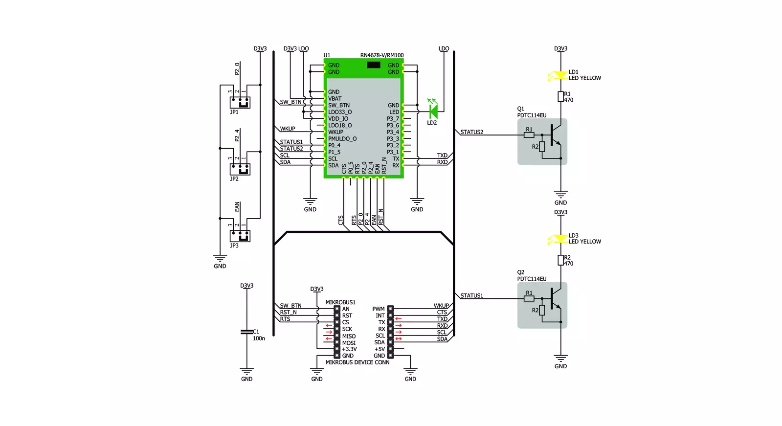
RN4678 Click is based on the RN4678, a Bluetooth® 4.2 dual-mode module from Microchip. This Click is designed to run on a 3.3V power supply. It communicates with the target microcontroller over I2C and UART interface, with additional functionality provided by the following pins on the mikroBUS™ line: AN, RST, CS, PWM, INT. The RN4678 from Microchip is a fully certified Bluetooth version 4.2 module. Use it to add Bluetooth wireless capability to your project.
The module includes an onboard Bluetooth stack, power management subsystem, 2.4 GHz transceiver, and RF power amplifier. Data transfer is achieved through Bluetooth by sending or receiving data through SPP in Bluetooth (BT) Classic mode and Transparent UART in BLE mode. The RN4678 contains an integral ceramic chip antenna. The RN4678 module has strong AES128 Encryption. 128-bit encryption is one of the most robust encryption algorithms. AES stands for
Advanced Encryption Standard, a symmetric encryption algorithm. This Click board™ can be operated only with a 3.3V logic voltage level. The board must perform appropriate logic voltage level conversion before using MCUs with different logic levels. Also, it comes equipped with a library containing functions and an example code that can be used, as a reference, for further development.

Features overview
Development board
Nucleo 32 with STM32F031K6 MCU board provides an affordable and flexible platform for experimenting with STM32 microcontrollers in 32-pin packages. Featuring Arduino™ Nano connectivity, it allows easy expansion with specialized shields, while being mbed-enabled for seamless integration with online resources. The
board includes an on-board ST-LINK/V2-1 debugger/programmer, supporting USB reenumeration with three interfaces: Virtual Com port, mass storage, and debug port. It offers a flexible power supply through either USB VBUS or an external source. Additionally, it includes three LEDs (LD1 for USB communication, LD2 for power,
and LD3 as a user LED) and a reset push button. The STM32 Nucleo-32 board is supported by various Integrated Development Environments (IDEs) such as IAR™, Keil®, and GCC-based IDEs like AC6 SW4STM32, making it a versatile tool for developers.

Microcontroller Overview
MCU Card / MCU

Architecture
ARM Cortex-M0
MCU Memory (KB)
32
Silicon Vendor
STMicroelectronics
Pin count
32
RAM (Bytes)
4096
You complete me!
Accessories
Click Shield for Nucleo-32 is the perfect way to expand your development board's functionalities with STM32 Nucleo-32 pinout. The Click Shield for Nucleo-32 provides two mikroBUS™ sockets to add any functionality from our ever-growing range of Click boards™. We are fully stocked with everything, from sensors and WiFi transceivers to motor control and audio amplifiers. The Click Shield for Nucleo-32 is compatible with the STM32 Nucleo-32 board, providing an affordable and flexible way for users to try out new ideas and quickly create prototypes with any STM32 microcontrollers, choosing from the various combinations of performance, power consumption, and features. The STM32 Nucleo-32 boards do not require any separate probe as they integrate the ST-LINK/V2-1 debugger/programmer and come with the STM32 comprehensive software HAL library and various packaged software examples. This development platform provides users with an effortless and common way to combine the STM32 Nucleo-32 footprint compatible board with their favorite Click boards™ in their upcoming projects.

Used MCU Pins
mikroBUS™ mapper
Take a closer look
Click board™ Schematic
Step by step
Project assembly

Start by selecting your development board and Click board™. Begin with the Nucleo 32 with STM32F031K6 MCU as your development board.


Software Support
Library Description
This library contains API for RN4678 Click driver.
Key functions:
rn4678_enter_command_mode- Enter the command mode functionrn4678_exit_command_mode- Exit the command mode functionrn4678_set_device_name- Set the device name function
Open Source
Code example
The complete application code and a ready-to-use project are available through the NECTO Studio Package Manager for direct installation in the NECTO Studio. The application code can also be found on the MIKROE GitHub account.
/*!
 * \file
 * \brief RN4678 Click example
 *
 * # Description
 * This example reads and processes data from RN4678 Clicks.
 *
 * The demo application is composed of two sections :
 *
 * ## Application Init
 * Initializes the driver and configures the Click board.
 *
 * ## Application Task
 * Checks for the received data, reads it and replies with a certain message.
 *
 * ## Additional Function
 * - rn4678_process ( ) - Logs all the received messages/responses on the USB UART,
 *                        and if it receives "Hello" string it sends the certain message
 *                        back to the connected device.
 *
 * @note
 * We have used the Serial Bluetooth Terminal smartphone application for the test.
 * A smartphone and the Click board must be paired in order to exchange messages with each other.
 *
 * \author MikroE Team
 *
 */
// ------------------------------------------------------------------- INCLUDES

#include "board.h"
#include "log.h"
#include "rn4678.h"
#include "string.h"

#define PROCESS_COUNTER 20
#define PROCESS_RX_BUFFER_SIZE 100
#define PROCESS_PARSER_BUFFER_SIZE 100

#define PROCESS_RSP_ERROR  -1
#define PROCESS_RSP_OK     1
#define PROCESS_NO_RSP     0
#define PROCESS_LOG_RSP    0

// ------------------------------------------------------------------ VARIABLES

static rn4678_t rn4678;
static log_t logger;

uint8_t DEVICE_NAME_DATA[ 20 ] = { 'R', 'N', '4', '6', '7', '8', ' ', 'c', 'l', 'i', 'c', 'k' };
uint8_t EXTENDED_STRING_DATA[ 10 ] = { 'S', 'l', 'a', 'v', 'e' };
uint8_t PIN_CODE_DATA[ 10 ] = { '1', '2', '3', '4' };
static char current_parser_buf[ PROCESS_PARSER_BUFFER_SIZE ];

// ------------------------------------------------------- ADDITIONAL FUNCTIONS

static int8_t rn4678_process ( char * response )
{
    int32_t rsp_size;
    uint16_t rsp_cnt = 0;

    char uart_rx_buffer[ PROCESS_RX_BUFFER_SIZE ] = { 0 };
    uint8_t check_buf_cnt;
    uint8_t process_cnt = PROCESS_COUNTER;
    int8_t rsp_flag = 0;

    // Clear current buffer
    memset( current_parser_buf, 0, PROCESS_PARSER_BUFFER_SIZE );

    while( process_cnt != 0 )
    {
        rsp_size = rn4678_generic_read( &rn4678, uart_rx_buffer, PROCESS_RX_BUFFER_SIZE );

        if ( rsp_size > 0 )
        {
            // Validation of the received data
            for ( check_buf_cnt = 0; check_buf_cnt < rsp_size; check_buf_cnt++ )
            {
                if ( uart_rx_buffer[ check_buf_cnt ] == 0 )
                {
                    uart_rx_buffer[ check_buf_cnt ] = 13;
                }
            }
            // Storages data in current buffer
            rsp_cnt += rsp_size;
            if ( rsp_cnt < PROCESS_PARSER_BUFFER_SIZE )
            {
                strncat( current_parser_buf, uart_rx_buffer, rsp_size );
            }

            // Clear RX buffer
            memset( uart_rx_buffer, 0, PROCESS_RX_BUFFER_SIZE );

            if ( strstr( current_parser_buf, "ERR" ) ) {
                Delay_100ms( );
                rsp_flag = PROCESS_RSP_ERROR;
                break;
            }

            if ( PROCESS_LOG_RSP != response )
            {
                if ( strstr( current_parser_buf, response ) ) {
                    Delay_100ms( );
                    rsp_flag = PROCESS_RSP_OK;
                    break;
                }
            }
            else
            {
                rsp_flag = PROCESS_RSP_OK;
                process_cnt = 1;
            }

            if ( strstr( current_parser_buf, "Hello" ) ) {
                rn4678_generic_write( &rn4678, "MikroE\r\n", 8 );
                Delay_100ms( );
                break;
            }
        }
        else
        {
            process_cnt--;

            // Process delay
            Delay_ms ( 100 );
        }
    }

    if ( PROCESS_NO_RSP != rsp_flag )
    {
        log_printf( &logger, "%s", current_parser_buf );
        log_printf( &logger, "\r\n---------------------------\r\n" );
        return rsp_flag;
    }

    return PROCESS_NO_RSP;
}

// ------------------------------------------------------ APPLICATION FUNCTIONS

void application_init ( void )
{
    log_cfg_t log_cfg;
    rn4678_cfg_t cfg;

    /**
     * Logger initialization.
     * Default baud rate: 115200
     * Default log level: LOG_LEVEL_DEBUG
     * @note If USB_UART_RX and USB_UART_TX
     * are defined as HAL_PIN_NC, you will
     * need to define them manually for log to work.
     * See @b LOG_MAP_USB_UART macro definition for detailed explanation.
     */
    LOG_MAP_USB_UART( log_cfg );
    log_init( &logger, &log_cfg );
    log_info( &logger, "---- Application Init ----" );

    //  Click initialization.

    rn4678_cfg_setup( &cfg );
    RN4678_MAP_MIKROBUS( cfg, MIKROBUS_1 );
    rn4678_init( &rn4678, &cfg );

    rn4678_enable ( &rn4678 );
    Delay_ms ( 1000 );
    rn4678_hw_reset ( &rn4678 );
    Delay_ms ( 1000 );

    log_printf( &logger, "Configuring the module...\n" );

    do
    {
        log_printf( &logger, " --- Command mode --- \r\n" );
        rn4678_enter_command_mode( &rn4678 );
    }
    while( rn4678_process( "CMD" ) != 1 );

    do
    {
        log_printf( &logger, " --- Device name --- \r\n" );
        rn4678_set_device_name( &rn4678, &DEVICE_NAME_DATA[ 0 ] );
    }
    while( rn4678_process( "AOK" ) != 1 );

    do
    {
        log_printf( &logger, " --- Status string --- \r\n" );
        rn4678_set_extended_status_string( &rn4678, &EXTENDED_STRING_DATA[ 0 ] );
    }
    while( rn4678_process( "AOK" ) != 1 );

    do
    {
        log_printf( &logger, " --- Operating mode --- \r\n" );
        rn4678_set_operating_mode( &rn4678, 0 );
    }
    while( rn4678_process( "AOK" ) != 1 );

    do
    {
        log_printf( &logger, " --- Authentication --- \r\n" );
        rn4678_set_authentication( &rn4678, 1 );
    }
    while( rn4678_process( "AOK" ) != 1 );

    do
    {
        log_printf( &logger, " --- Pin code --- \r\n" );
        rn4678_set_security_pin_code( &rn4678, &PIN_CODE_DATA[ 0 ] );
    }
    while( rn4678_process( "AOK" ) != 1 );

    do
    {
        log_printf( &logger, " --- Exit command mode --- \r\n" );
        rn4678_exit_command_mode( &rn4678 );
    }
    while( rn4678_process( "END" ) != 1 );

    log_printf( &logger, "The module has been configured.\n" );

    rn4678_set_cts_pin( &rn4678, 0 );
}

void application_task ( void )
{
    rn4678_process( PROCESS_LOG_RSP );
}

int main ( void )
{
    /* Do not remove this line or clock might not be set correctly. */
    #ifdef PREINIT_SUPPORTED
    preinit();
    #endif

    application_init( );

    for ( ; ; )
    {
        application_task( );
    }

    return 0;
}


// ------------------------------------------------------------------------ END
Additional Support
Resources
Category:BT/BLE


