Experience the future of parameter adjustments with PTA3043-2015CPB103 and STM32F031K6
Slide to precision: Our mechanical slider potentiometer elevates control

Published Oct 01, 2024
Click board™
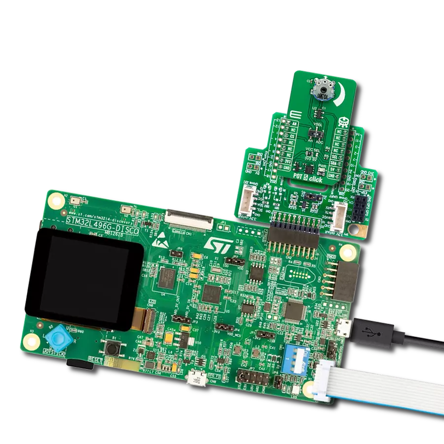
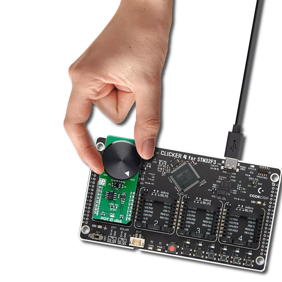
Slider 2 Click
Dev. board
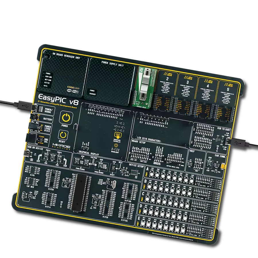
Nucleo 32 with STM32F031K6 MCU
Compiler
NECTO Studio
MCU
STM32F031K6
We aim to empower your projects with the precision and reliability of our slider potentiometer, offering seamless adjustments and control for a wide range of uses
A
A
Hardware Overview
How does it work?
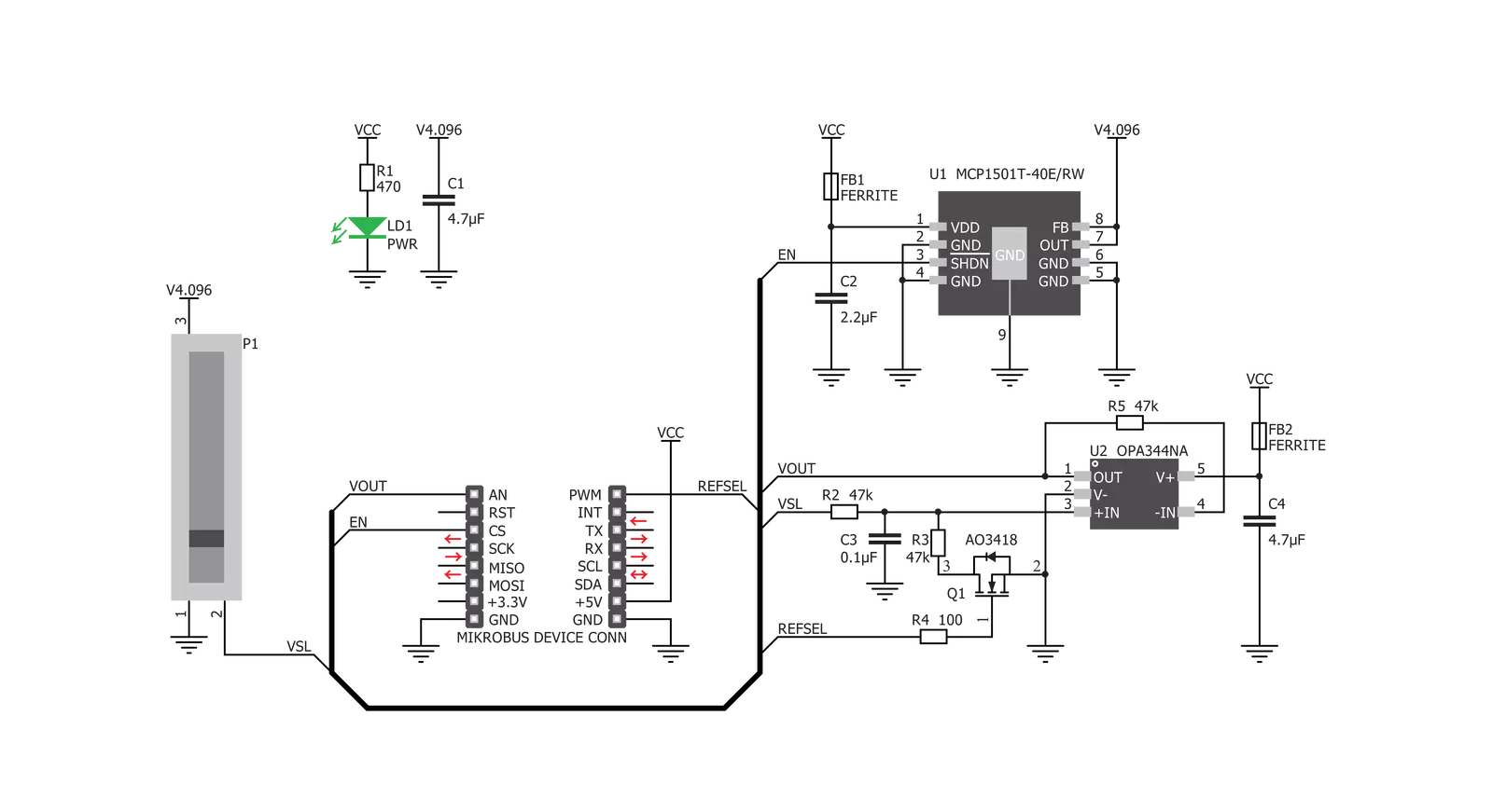
Slider 2 Click is based on the PTA3043, a linear, high-grade, 10K potentiometer from Bourns. This potentiometer has a 30 mm travel distance. The long travel distance of the wiper allows more accurate movements and combined with the high-quality manufacturing process it allows to dial-in the desired voltage with ease. This type of potentiometers are also known as sliders, thus the name for this Click board™. The potentiometer has a small dent in the middle, which enables tactile feedback when the center position is reached. The potentiometer is connected between the VREF and GND, acting as a voltage divider. Its wiper terminal outputs voltage in the range from 0 to 4.096V, depending on its position. The used potentiometer is linear, so the wiper potential changes linearly with its position. The voltage reference(VREF) is obtained from the MCP1501, a high-precision voltage reference IC from Microchip. The main purpose of this IC is to provide and retain a very accurate voltage of
4.096V. Its voltage reference is accurate enough for most applications where the analog output from the Slider 2 click can be utilized as a control voltage signal (CV). The output is buffered with a rail-to-rail, low-power operational amplifier, labeled as OPA344, produced by Texas Instruments. After the buffering op-amp, the output signal is delivered at the AN pin of the mikroBUS, labeled as VO on this Click Board, so it can be easily sampled by the internal A/D converter of the host microcontroller unit (MCU. Most MCUs have A/D peripherals that can use 4.096 as the reference voltage for the full-scale value (PIC 8-bit family is a good example). However, there are many cases where 2.048V is more adequate, so the Click board offers a choice: if there is a HIGH logic level at the RSL pin, the N-type MOSFET will open and another resistor will be introduced to the circuit. A voltage divider will be formed at the input of the buffering op-amp, which will halve the voltage from the potentiometer, reducing its maximum
value to 2.048V. When the logic level at the RSL pin is LOW, the N-type MOSFET will stay closed, so the second resistor of the voltage divider remains isolated. This will cause the full voltage level from the potentiometer to appear at the VO pin of the Click Board, in the range from 0 to 4.096V max. The MCP1501 IC has the #SHDN pin, used to shut down the IC when it's set to a LOW logic level. When this pin is set to a LOW logic level, the voltage reference output will be turned OFF, so there will be no voltage changes at the VO pin. By enabling the MCP1501 the voltage reference is established once again, so the Click Board can deliver an analog signal with the voltage ranging from 0 to 4.096V, or from 0 to 2.048V if the RSL pin is set to a HIGH logic level. It is recommended to start up the Click Board with the EN pin at the LOW logic level, to allow the internal power supply of the MCP1501 to reach its operational values.


Features overview
Development board
Nucleo 32 with STM32F031K6 MCU board provides an affordable and flexible platform for experimenting with STM32 microcontrollers in 32-pin packages. Featuring Arduino™ Nano connectivity, it allows easy expansion with specialized shields, while being mbed-enabled for seamless integration with online resources. The
board includes an on-board ST-LINK/V2-1 debugger/programmer, supporting USB reenumeration with three interfaces: Virtual Com port, mass storage, and debug port. It offers a flexible power supply through either USB VBUS or an external source. Additionally, it includes three LEDs (LD1 for USB communication, LD2 for power,
and LD3 as a user LED) and a reset push button. The STM32 Nucleo-32 board is supported by various Integrated Development Environments (IDEs) such as IAR™, Keil®, and GCC-based IDEs like AC6 SW4STM32, making it a versatile tool for developers.

Microcontroller Overview
MCU Card / MCU

Architecture
ARM Cortex-M0
MCU Memory (KB)
32
Silicon Vendor
STMicroelectronics
Pin count
32
RAM (Bytes)
4096
You complete me!
Accessories
Click Shield for Nucleo-32 is the perfect way to expand your development board's functionalities with STM32 Nucleo-32 pinout. The Click Shield for Nucleo-32 provides two mikroBUS™ sockets to add any functionality from our ever-growing range of Click boards™. We are fully stocked with everything, from sensors and WiFi transceivers to motor control and audio amplifiers. The Click Shield for Nucleo-32 is compatible with the STM32 Nucleo-32 board, providing an affordable and flexible way for users to try out new ideas and quickly create prototypes with any STM32 microcontrollers, choosing from the various combinations of performance, power consumption, and features. The STM32 Nucleo-32 boards do not require any separate probe as they integrate the ST-LINK/V2-1 debugger/programmer and come with the STM32 comprehensive software HAL library and various packaged software examples. This development platform provides users with an effortless and common way to combine the STM32 Nucleo-32 footprint compatible board with their favorite Click boards™ in their upcoming projects.

Used MCU Pins
mikroBUS™ mapper
Take a closer look
Click board™ Schematic
Step by step
Project assembly

Start by selecting your development board and Click board™. Begin with the Nucleo 32 with STM32F031K6 MCU as your development board.


Software Support
Library Description
This library contains API for Slider 2 Click driver.
Key functions:
slider2_enable- This function sets desired state to EN pinslider2_set_reference- This function sets desired reference to RSL pin
Open Source
Code example
The complete application code and a ready-to-use project are available through the NECTO Studio Package Manager for direct installation in the NECTO Studio. The application code can also be found on the MIKROE GitHub account.
/*!
 * \file
 * \brief Slider2 Click example
 *
 * # Description
 * This Click utilizes potentiometer with long travel distance of the wiper
 * witch allows more accurate movements and combined with the high-quality
 * manufacturing process it allows to dial-in the desired voltage with ease.
 * Its wiper terminal outputs voltage in the range from 0 to 4.096V.
 * The used potentiometer is linear, so the wiper potential changes linearly with its position.
 *
 * The demo application is composed of two sections :
 *
 * ## Application Init
 * Initialization driver init and ADC init.
 *
 * ## Application Task
 * Read Slider data value and this data logs to USBUART every 500ms.
 *
 *
 * \author MikroE Team
 *
 */
// ------------------------------------------------------------------- INCLUDES

#include "board.h"
#include "log.h"
#include "slider2.h"

// ------------------------------------------------------------------ VARIABLES

static slider2_t slider2;
static log_t logger;


// ------------------------------------------------------ APPLICATION FUNCTIONS

void application_init ( void )
{
    log_cfg_t log_cfg;
    slider2_cfg_t cfg;

    /**
     * Logger initialization.
     * Default baud rate: 115200
     * Default log level: LOG_LEVEL_DEBUG
     * @note If USB_UART_RX and USB_UART_TX
     * are defined as HAL_PIN_NC, you will
     * need to define them manually for log to work.
     * See @b LOG_MAP_USB_UART macro definition for detailed explanation.
     */
    LOG_MAP_USB_UART( log_cfg );
    log_init( &logger, &log_cfg );
    log_info( &logger, "---- Application Init ----" );

    //  Click initialization.

    slider2_cfg_setup( &cfg );
    SLIDER2_MAP_MIKROBUS( cfg, MIKROBUS_1 );
    slider2_init( &slider2, &cfg );
    slider2_default_cfg( &slider2);

}

void application_task ( void )
{
    slider2_data_t tmp;

    //  Task implementation.

    tmp = slider2_generic_read ( &slider2 );
    log_printf( &logger, "** ADC value : [DEC]- %d, [HEX]- 0x%x \r\n", tmp, tmp );

    Delay_ms ( 500 );

}

int main ( void )
{
    /* Do not remove this line or clock might not be set correctly. */
    #ifdef PREINIT_SUPPORTED
    preinit();
    #endif

    application_init( );

    for ( ; ; )
    {
        application_task( );
    }

    return 0;
}

// ------------------------------------------------------------------------ END
Additional Support
Resources
Category:Potentiometers