Convert a higher input voltage to a lower output easily with TPS628510 and STM32F031K6
Synchronous step-down supremacy!

Published Oct 01, 2024
Click board™
Step Down 5 Click
Dev Board
Nucleo 32 with STM32F031K6 MCU
Compiler
NECTO Studio
MCU
STM32F031K6
Unlocking the full potential of modern electronics, our step-down converter harmonizes power requirements, paving the way for energy-conscious innovations
A
A
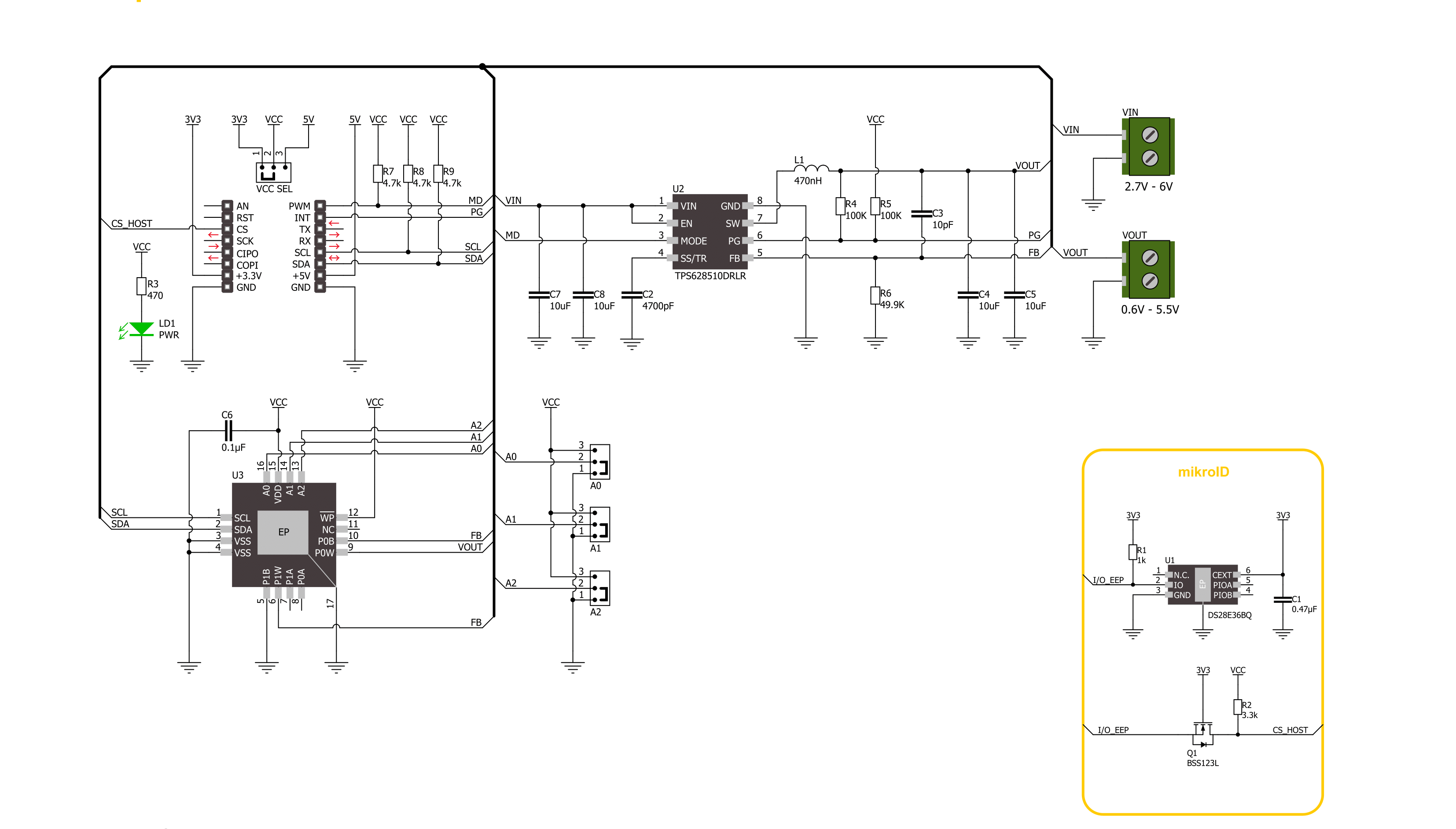
Hardware Overview
How does it work?
Step Down 5 Click is based on the TPS628510, a synchronous step-down converter from Texas Instruments, providing interface-configurable output voltage range from 0.6V to 5.5V suitable for point-of-load and post-regulation applications. This synchronous switch mode power converter is based on a peak current mode control topology and achieves fast and stable operation with an internally compensated control loop. It provides up to 0.5A load current over a wide input supply range from 2.7V to 6V and has excellent load and line regulation. In addition, it is characterized by high efficiency over a wide range of load output voltage from 0.6V to 5.5V, which can be easily adjusted using a digital potentiometer, the MCP4661 from Microchip. The TPS628510 supports
forced fixed frequency PWM operation with the MD pin of the mikroBUS™ socket set to a high logic level. Its switching frequency is internally fixed at 2.25MHz. When the MD pin is set to a low logic level, the TPS628510 operates in power save mode (PFM) at a low output current and automatically transfers to fixed-frequency PWM mode at a higher output current. In PFM mode, the switching frequency decreases linearly based on the load to sustain high efficiency down to a very low output current. Alternatively, the TPS628510 can be synchronized to an external clock signal from 1.8MHz to 4MHz, applied to the MD pin. An internal PLL allows you to change from an internal clock to an external clock during operation. Besides the operational mode
selection pin, this Click board™ also has a power-good function routed to the PG pin of the mikroBUS™ socket, indicating that the output reached desired regulation and the possibility for the MCP4661 to choose the least significant bit (LSB) of its I2C slave address by positioning SMD jumpers labeled as ADDR SEL to an appropriate position marked as 0 and 1. This Click board™ can operate with either 3.3V or 5V logic voltage levels selected via the VCC SEL jumper. This way, both 3.3V and 5V capable MCUs can use the communication lines properly. Also, this Click board™ comes equipped with a library containing easy-to-use functions and an example code that can be used, as a reference, for further development.

Features overview
Development board
Nucleo 32 with STM32F031K6 MCU board provides an affordable and flexible platform for experimenting with STM32 microcontrollers in 32-pin packages. Featuring Arduino™ Nano connectivity, it allows easy expansion with specialized shields, while being mbed-enabled for seamless integration with online resources. The
board includes an on-board ST-LINK/V2-1 debugger/programmer, supporting USB reenumeration with three interfaces: Virtual Com port, mass storage, and debug port. It offers a flexible power supply through either USB VBUS or an external source. Additionally, it includes three LEDs (LD1 for USB communication, LD2 for power,
and LD3 as a user LED) and a reset push button. The STM32 Nucleo-32 board is supported by various Integrated Development Environments (IDEs) such as IAR™, Keil®, and GCC-based IDEs like AC6 SW4STM32, making it a versatile tool for developers.

Microcontroller Overview
MCU Card / MCU

Architecture
ARM Cortex-M0
MCU Memory (KB)
32
Silicon Vendor
STMicroelectronics
Pin count
32
RAM (Bytes)
4096
You complete me!
Accessories
Click Shield for Nucleo-32 is the perfect way to expand your development board's functionalities with STM32 Nucleo-32 pinout. The Click Shield for Nucleo-32 provides two mikroBUS™ sockets to add any functionality from our ever-growing range of Click boards™. We are fully stocked with everything, from sensors and WiFi transceivers to motor control and audio amplifiers. The Click Shield for Nucleo-32 is compatible with the STM32 Nucleo-32 board, providing an affordable and flexible way for users to try out new ideas and quickly create prototypes with any STM32 microcontrollers, choosing from the various combinations of performance, power consumption, and features. The STM32 Nucleo-32 boards do not require any separate probe as they integrate the ST-LINK/V2-1 debugger/programmer and come with the STM32 comprehensive software HAL library and various packaged software examples. This development platform provides users with an effortless and common way to combine the STM32 Nucleo-32 footprint compatible board with their favorite Click boards™ in their upcoming projects.

Used MCU Pins
mikroBUS™ mapper
Take a closer look
Schematic
Step by step
Project assembly

Start by selecting your development board and Click board™. Begin with the Nucleo 32 with STM32F031K6 MCU as your development board.


Track your results in real time
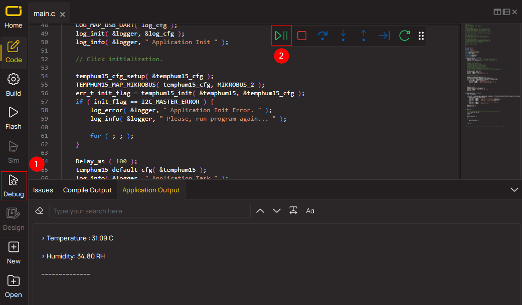
Application Output via Debug Mode
1. Once the code example is loaded, pressing the "DEBUG" button initiates the build process, programs it on the created setup, and enters Debug mode.
2. After the programming is completed, a header with buttons for various actions within the IDE becomes visible. Clicking the green "PLAY" button starts reading the results achieved with the Click board™. The achieved results are displayed in the Application Output tab.
Software Support
Library Description
This library contains API for Step Down 5 Click driver.
Key functions:
stepdown5_set_wiper_0_pos- Step Down 5 set wiper 0 positionstepdown5_set_r1_resistance- Step Down 5 set potentiometer 0 resistancestepdown5_set_output- Step Down 5 set output voltage
Open Source
Code example
This example can be found in NECTO Studio. Feel free to download the code, or you can copy the code below.
/*!
 * @file main.c
 * @brief Step Down 5 Click example
 *
 * # Description
 * This library contains API for the Step Down 5 Click driver.
 * This driver provides the functions to set the output voltage treshold.
 *
 * The demo application is composed of two sections :
 *
 * ## Application Init
 * Initialization of I2C module and log UART.
 * After driver initialization, default settings sets output voltage to 0.6 V.
 *
 * ## Application Task
 * This example demonstrates the use of the Step Down 5 Click board™ by changing
 * output voltage every 5 seconds starting from 0.6 V up to 3.3 V.
 *
 *
 * @author Stefan Ilic
 *
 */

#include "board.h"
#include "log.h"
#include "stepdown5.h"

static stepdown5_t stepdown5;
static log_t logger;

/**
 * @brief Output level printing function.
 * @details This function is used to log value of the selected voltage to UART terminal.
 * @param[in] sel_level : Selected voltage level.
 * @return Nothing.
 * @note None.
 */
static void print_selected_output_level ( uint8_t sel_level );

void application_init ( void )
{
    log_cfg_t log_cfg;  /**< Logger config object. */
    stepdown5_cfg_t stepdown5_cfg;  /**< Click config object. */

    /**
     * Logger initialization.
     * Default baud rate: 115200
     * Default log level: LOG_LEVEL_DEBUG
     * @note If USB_UART_RX and USB_UART_TX
     * are defined as HAL_PIN_NC, you will
     * need to define them manually for log to work.
     * See @b LOG_MAP_USB_UART macro definition for detailed explanation.
     */
    LOG_MAP_USB_UART( log_cfg );
    log_init( &logger, &log_cfg );
    log_info( &logger, " Application Init " );

    // Click initialization.
    stepdown5_cfg_setup( &stepdown5_cfg );
    STEPDOWN5_MAP_MIKROBUS( stepdown5_cfg, MIKROBUS_1 );
    if ( I2C_MASTER_ERROR == stepdown5_init( &stepdown5, &stepdown5_cfg ) )
    {
        log_error( &logger, " Communication init." );
        for ( ; ; );
    }

    if ( STEPDOWN5_ERROR == stepdown5_default_cfg ( &stepdown5 ) )
    {
        log_error( &logger, " Default configuration." );
        for ( ; ; );
    }

    log_info( &logger, " Application Task " );
}

void application_task ( void )
{
    for ( uint8_t n_cnt = STEPDOWN5_OUTPUT_0V6; n_cnt <= STEPDOWN5_OUTPUT_3V3; n_cnt++ )
    {
        stepdown5_set_output( &stepdown5, n_cnt );
        log_printf( &logger, " Selected output is:" );
        print_selected_output_level ( n_cnt );
        Delay_ms( 5000 );
    }
}

void main ( void )
{
    application_init( );

    for ( ; ; )
    {
        application_task( );
    }
}

static void print_selected_output_level ( uint8_t sel_level )
{
    switch ( sel_level )
    {
        case ( STEPDOWN5_OUTPUT_0V6 ):
        {
            log_printf( &logger, " 0.6V\r\n" );
            break;
        }
        case ( STEPDOWN5_OUTPUT_1V5 ):
        {
            log_printf( &logger, " 1.5V\r\n" );
            break;
        }
        case ( STEPDOWN5_OUTPUT_2V5 ):
        {
            log_printf( &logger, " 2.5V\r\n" );
            break;
        }
        case ( STEPDOWN5_OUTPUT_3V3 ):
        {
            log_printf( &logger, " 3.3V\r\n" );
            break;
        }
        default:
        {
            log_printf( &logger, " ERROR\r\n" );
        }
    }
}

// ------------------------------------------------------------------------ END


