Combine MPR121 with STM32F031K6 and create any capacitive application you can think of
Seven clamps, endless possibilities!
Published Oct 01, 2024
Click board™
TouchClamp Click
Dev. board
Nucleo 32 with STM32F031K6 MCU
Compiler
NECTO Studio
MCU
STM32F031K6
Designed to enhance user experience, our solution facilitates the seamless integration of conductive materials, allowing them to serve as intuitive input buttons
A
A
Hardware Overview
How does it work?
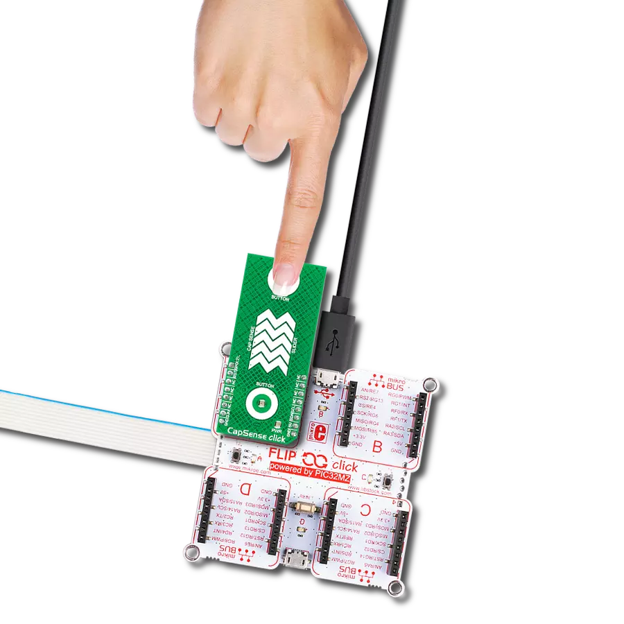
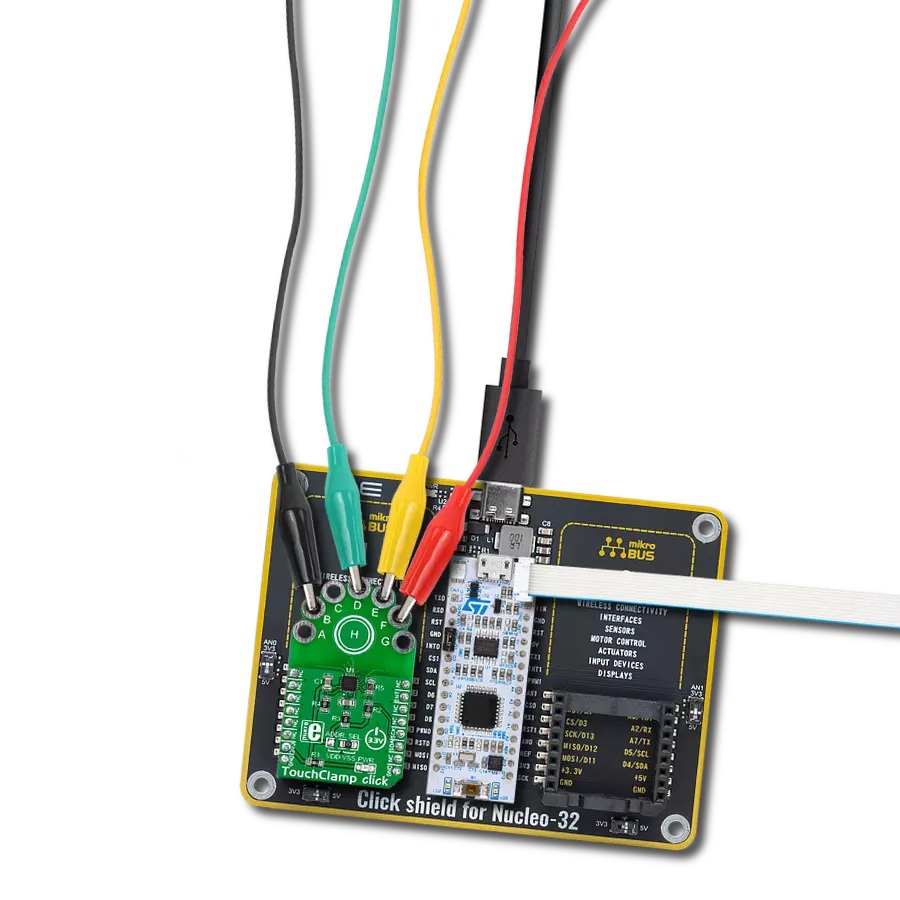
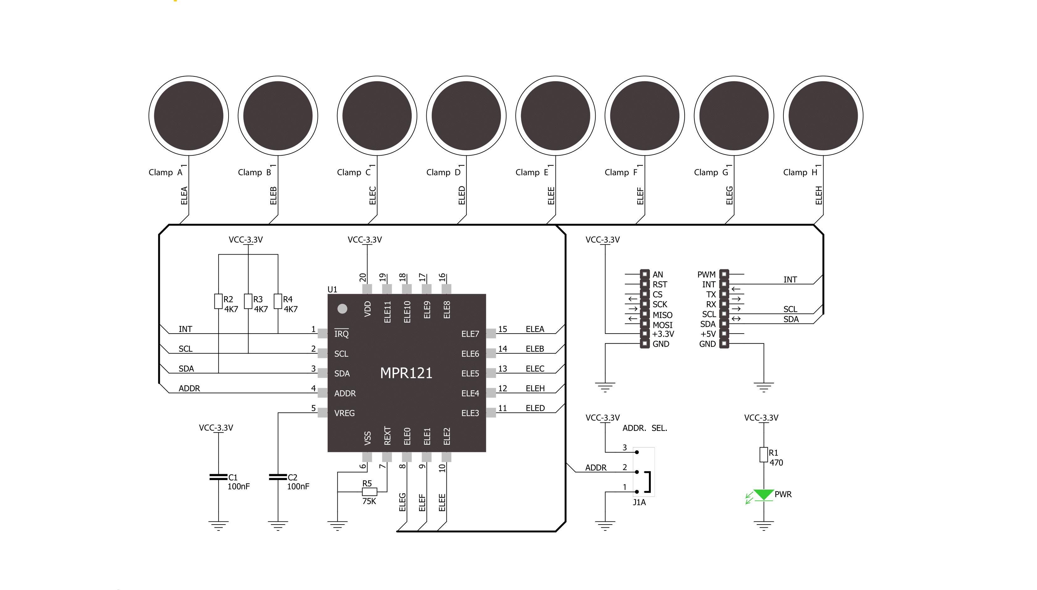
TouchClamp Click is based on the MPR121, a proximity capacitive touch sensor controller from NXP Semiconductors. The MPR121 uses seven electrodes/capacitance sensing inputs, four of which are multifunctional for LED driving (H, C, B, A) and GPIO. One electrode is an extra capacitive button in the middle of the board labeled H. It also features the 8th simulated electrode, which represents the simultaneous charging of all electrodes connected together. The MPR121 has integrated independent autocalibration and autoconfiguration for each electrode input and separate touch and release trip thresholds for each, providing hysteresis and electrode independence. The easiest way to experiment with TouchClamp click is to use wires with alligator clips. Let your imagination roam free when choosing conductive objects such as cans, fruit, jar lids, and more. The MPR121 chip has several features in addition that simplify development and integration. First, it applies three levels of digital filtering to the raw ADC data to remove high and low-frequency noise, ensuring that
the interrupts are properly registered in a broad range of applications. The auto-calibration function, according to the vendor's datasheet, "continually learns the background baseline capacitance of each individual electrode, so the system only has to program the amount of small change from these baselines that represents a touch or release." The auto-configuration uses the given target charge level so the chip can automatically run to get an optimized charge current and charge time setting for each electrode without knowing the specific capacitance value on the electrode input. The capacitance sensing uses a constant DC current capacitance sensing scheme and can measure capacitances ranging from 10pF to over 2000pF, with resolutions up to 0.01pF. The voltage measured on the input sensing node is inversely proportional to the capacitance and is sampled by an internal 10-bit ADC. The touch sensing compares the baseline value with the current immediate electrode data to determine if a touch or a release has occurred, with the ability to set a touch/release threshold.
The proximity sensing acts as the near proximity sensing system, where all electrodes can be summoned together to create a single large electrode, thus covering a much larger area. Touch sensing and proximity sensing can be used at the same time. Among 12 electrodes, eight of them can be used as a GPIO and can be used to drive LEDs or for GPIO. The TouchClamp Click uses an I2C 2-Wire interface to communicate with the host MCU. It also has an ADDR SEL jumper to choose between the two available I2C addresses and can be connected to VDD or VSS (VSS position set by default). In addition, the TouchClamp Click comes with an interrupt INT pin, which is triggered anytime a touch or release is detected. This Click board™ can be operated only with a 3.3V logic voltage level. The board must perform appropriate logic voltage level conversion before using MCUs with different logic levels. Also, this Click board™ comes equipped with a library containing easy-to-use functions and an example code that can be used as a reference for further development.

Features overview
Development board
Nucleo 32 with STM32F031K6 MCU board provides an affordable and flexible platform for experimenting with STM32 microcontrollers in 32-pin packages. Featuring Arduino™ Nano connectivity, it allows easy expansion with specialized shields, while being mbed-enabled for seamless integration with online resources. The
board includes an on-board ST-LINK/V2-1 debugger/programmer, supporting USB reenumeration with three interfaces: Virtual Com port, mass storage, and debug port. It offers a flexible power supply through either USB VBUS or an external source. Additionally, it includes three LEDs (LD1 for USB communication, LD2 for power,
and LD3 as a user LED) and a reset push button. The STM32 Nucleo-32 board is supported by various Integrated Development Environments (IDEs) such as IAR™, Keil®, and GCC-based IDEs like AC6 SW4STM32, making it a versatile tool for developers.

Microcontroller Overview
MCU Card / MCU

Architecture
ARM Cortex-M0
MCU Memory (KB)
32
Silicon Vendor
STMicroelectronics
Pin count
32
RAM (Bytes)
4096
You complete me!
Accessories
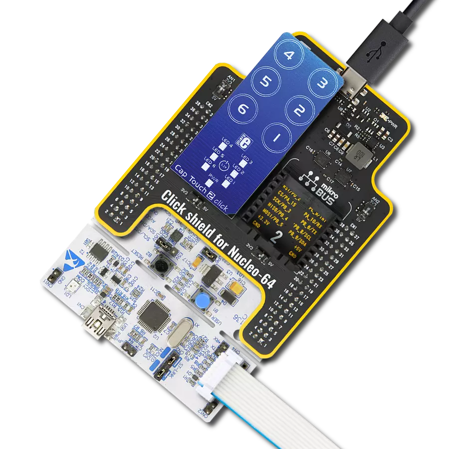
Click Shield for Nucleo-32 is the perfect way to expand your development board's functionalities with STM32 Nucleo-32 pinout. The Click Shield for Nucleo-32 provides two mikroBUS™ sockets to add any functionality from our ever-growing range of Click boards™. We are fully stocked with everything, from sensors and WiFi transceivers to motor control and audio amplifiers. The Click Shield for Nucleo-32 is compatible with the STM32 Nucleo-32 board, providing an affordable and flexible way for users to try out new ideas and quickly create prototypes with any STM32 microcontrollers, choosing from the various combinations of performance, power consumption, and features. The STM32 Nucleo-32 boards do not require any separate probe as they integrate the ST-LINK/V2-1 debugger/programmer and come with the STM32 comprehensive software HAL library and various packaged software examples. This development platform provides users with an effortless and common way to combine the STM32 Nucleo-32 footprint compatible board with their favorite Click boards™ in their upcoming projects.

Used MCU Pins
mikroBUS™ mapper
Take a closer look
Click board™ Schematic
Step by step
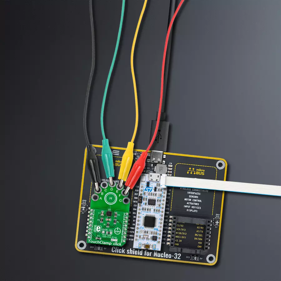
Project assembly

Start by selecting your development board and Click board™. Begin with the Nucleo 32 with STM32F031K6 MCU as your development board.


Track your results in real time
Application Output
1. Application Output - In Debug mode, the 'Application Output' window enables real-time data monitoring, offering direct insight into execution results. Ensure proper data display by configuring the environment correctly using the provided tutorial.

2. UART Terminal - Use the UART Terminal to monitor data transmission via a USB to UART converter, allowing direct communication between the Click board™ and your development system. Configure the baud rate and other serial settings according to your project's requirements to ensure proper functionality. For step-by-step setup instructions, refer to the provided tutorial.

3. Plot Output - The Plot feature offers a powerful way to visualize real-time sensor data, enabling trend analysis, debugging, and comparison of multiple data points. To set it up correctly, follow the provided tutorial, which includes a step-by-step example of using the Plot feature to display Click board™ readings. To use the Plot feature in your code, use the function: plot(*insert_graph_name*, variable_name);. This is a general format, and it is up to the user to replace 'insert_graph_name' with the actual graph name and 'variable_name' with the parameter to be displayed.

Software Support
Library Description
This library contains API for TouchClamp Click driver.
Key functions:
etouchclamp_get_touch_data- Get touch data function
Open Source
Code example
The complete application code and a ready-to-use project are available through the NECTO Studio Package Manager for direct installation in the NECTO Studio. The application code can also be found on the MIKROE GitHub account.
/*!
 * \file
 * \brief TouchClamp Click example
 *
 * # Description
 * This demo-app shows the touch position using TouchClamp Click.
 *
 * The demo application is composed of two sections :
 *
 * ## Application Init
 * Configuring Clicks and log objects.
 * Setting the Click in the default configuration.
 *
 * ## Application Task
 * Detect and dispay touch position when the Click is triggered.
 *
 * \author Nenad Filipovic
 *
 */
// ------------------------------------------------------------------- INCLUDES

#include "board.h"
#include "log.h"
#include "touchclamp.h"

// ------------------------------------------------------------------ VARIABLES

static touchclamp_t touchclamp;
static log_t logger;
uint16_t touch_data;
uint16_t touch_data_old;

// ------------------------------------------------------ APPLICATION FUNCTIONS

void application_init ( void )
{
    log_cfg_t log_cfg;
    touchclamp_cfg_t cfg;

    /**
     * Logger initialization.
     * Default baud rate: 115200
     * Default log level: LOG_LEVEL_DEBUG
     * @note If USB_UART_RX and USB_UART_TX
     * are defined as HAL_PIN_NC, you will
     * need to define them manually for log to work.
     * See @b LOG_MAP_USB_UART macro definition for detailed explanation.
     */
    LOG_MAP_USB_UART( log_cfg );
    log_init( &logger, &log_cfg );
    log_info( &logger, "---- Application Init ----" );

    //  Click initialization.

    touchclamp_cfg_setup( &cfg );
    TOUCHCLAMP_MAP_MIKROBUS( cfg, MIKROBUS_1 );
    touchclamp_init( &touchclamp, &cfg );
    Delay_ms ( 100 );

    touchclamp_soft_reset( &touchclamp );
    Delay_ms ( 100 );

    touchclamp_default_cfg( &touchclamp );
    Delay_ms ( 100 );

    touch_data_old = TOUCHCLAMP_NO_TOUCH;

    log_printf( &logger, "-------------------\r\n" );
    log_printf( &logger, " Touch Clamp Click \r\n" );
    log_printf( &logger, "-------------------\r\n" );
}

void application_task ( void )
{
    touch_data = touchclamp_get_touch_data( &touchclamp );

    if ( touch_data_old != touch_data )
    {
        if ( touch_data == TOUCHCLAMP_TOUCH_POSITION_H )
            log_printf( &logger, "  - - - - - - - H\r\n" );

        if ( touch_data == TOUCHCLAMP_TOUCH_POSITION_G )
            log_printf( &logger, "  - - - - - - G -\r\n" );

        if ( touch_data == TOUCHCLAMP_TOUCH_POSITION_F )
            log_printf( &logger, "  - - - - - F - -\r\n" );

        if ( touch_data == TOUCHCLAMP_TOUCH_POSITION_E )
            log_printf( &logger, "  - - - - E - - -\r\n" );

        if ( touch_data == TOUCHCLAMP_TOUCH_POSITION_D )
            log_printf( &logger, "  - - - D - - - -\r\n" );

        if ( touch_data == TOUCHCLAMP_TOUCH_POSITION_C )
            log_printf( &logger, "  - - C - - - - -\r\n" );

        if ( touch_data == TOUCHCLAMP_TOUCH_POSITION_B )
            log_printf( &logger, "  - B - - - - - -\r\n" );

        if ( touch_data == TOUCHCLAMP_TOUCH_POSITION_A )
            log_printf( &logger, "  A - - - - - - -\r\n" );

        touch_data_old = touch_data;
    }
}

int main ( void )
{
    /* Do not remove this line or clock might not be set correctly. */
    #ifdef PREINIT_SUPPORTED
    preinit();
    #endif

    application_init( );

    for ( ; ; )
    {
        application_task( );
    }

    return 0;
}


// ------------------------------------------------------------------------ END
Additional Support
Resources
Category:Capacitive