Maximize efficiency with precise current measurement using FAN4010 and PIC32MZ2048EFH100
Precision for every Amp!
Published Aug 10, 2023
Click board™
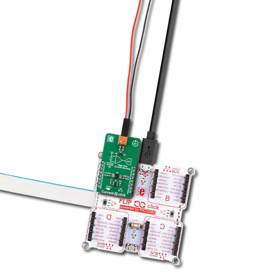
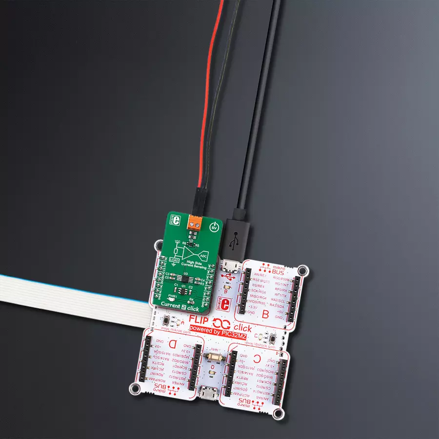
Current 2 Click
Dev. board
Flip&Click PIC32MZ
Compiler
NECTO Studio
MCU
PIC32MZ2048EFH100
Employ our precise current measurement solution to streamline operations, maximize energy utilization, and ensure system reliability
A
A
Hardware Overview
How does it work?
Current 2 Click is based on the FAN4010, a high-side current sensor by ON Semiconductor. This integrated circuit is a transimpedance amplifier suitable for the current sensing through the shunt resistor on the high side, between the power supply and the connected load. This allows the short circuit on the load to be sensed and will not disturb the GND reference of the connected load since the shunt resistor between the load negative connection terminal and the GND is avoided. These advantages benefit battery charging applications and gauges since short circuit detection is important. Also, the negative terminal of the battery has to stay on the same potential as the GND for the temperature output to be accurate, which is impossible with the low-side shunt resistor. A similar schematic could be designed using only operational amplifiers; however, due to the high inaccuracy of such a design (as the offset voltage of a typical
operational amplifier can greatly affect the output current, especially after the amplification is applied) and the low common mode voltage that typical operational amplifier can withstand, specialized current sensing amplifier ICs (CSA) such as the FAN4010, are used instead. The FAN4010 features an extremely low current offset of only 2 µA, which allows very accurate measurement within the 0.2% margin. The transconductance ratio at the output of the FAN4010 is 10mA/V, where V represents the voltage across the shunt resistor. The current at the output linearly depends on the current through the load. Using the appropriate resistor between the output and the GND, this current can be scaled to a proper voltage level to be used as the input for the A/D converter, the MCP3001, a 10-bit A/D converter (ADC) with SPI interface from Microchip. It is a high-performance, low-noise single-supply ADC that can deliver up to 200,000
samples per second (200 kbps). This makes it well-suited for fast-monitoring applications. It is also equipped with the reference input pin, allowing it to use an accurate voltage reference, which ensures very high sampling accuracy. Combined with the MCP1501-20 IC, a high-precision, buffered voltage reference of 2.048V, it is used with enough headroom to sample load current up to 4 A (4 A = 2 V at the ADC input). The calculation formulas can be derived from the datasheet of the FAN4010. However, it is unnecessary to perform any calculations if using mikroSDK-compatible functions provided for this Click board™. These functions already contain all the necessary calculations and output the current through the connected load directly in physical units [mA]. The included example demonstrates their practical usage.

Features overview
Development board
Flip&Click PIC32MZ is a compact development board designed as a complete solution that brings the flexibility of add-on Click boards™ to your favorite microcontroller, making it a perfect starter kit for implementing your ideas. It comes with an onboard 32-bit PIC32MZ microcontroller, the PIC32MZ2048EFH100 from Microchip, four mikroBUS™ sockets for Click board™ connectivity, two USB connectors, LED indicators, buttons, debugger/programmer connectors, and two headers compatible with Arduino-UNO pinout. Thanks to innovative manufacturing technology,
it allows you to build gadgets with unique functionalities and features quickly. Each part of the Flip&Click PIC32MZ development kit contains the components necessary for the most efficient operation of the same board. In addition, there is the possibility of choosing the Flip&Click PIC32MZ programming method, using the chipKIT bootloader (Arduino-style development environment) or our USB HID bootloader using mikroC, mikroBasic, and mikroPascal for PIC32. This kit includes a clean and regulated power supply block through the USB Type-C (USB-C) connector. All communication
methods that mikroBUS™ itself supports are on this board, including the well-established mikroBUS™ socket, user-configurable buttons, and LED indicators. Flip&Click PIC32MZ development kit allows you to create a new application in minutes. Natively supported by Mikroe software tools, it covers many aspects of prototyping thanks to a considerable number of different Click boards™ (over a thousand boards), the number of which is growing every day.

Microcontroller Overview
MCU Card / MCU

Architecture
PIC32
MCU Memory (KB)
2048
Silicon Vendor
Microchip
Pin count
100
RAM (Bytes)
524288
Used MCU Pins
mikroBUS™ mapper
Take a closer look
Click board™ Schematic

Step by step
Project assembly

Start by selecting your development board and Click board™. Begin with the Flip&Click PIC32MZ as your development board.


Software Support
Library Description
This library contains API for Current 2 Click driver.
Key functions:
current2_get_adc- Get ADC functioncurrent2_get_average_adc- Get averaged ADC functioncurrent2_get_current- Get current function
Open Source
Code example
The complete application code and a ready-to-use project are available through the NECTO Studio Package Manager for direct installation in the NECTO Studio. The application code can also be found on the MIKROE GitHub account.
/*!
* \file
* \brief current2 Click example
*
* # Description
* This application measures current.
*
* The demo application is composed of two sections :
*
* ## Application Init
* Initializes SPI interface in Mode 0
*
* ## Application Task
* Reads the current averaged result of 20 samples and
* gets this result in a proper value [mA]. Repeats the current reading every 500ms.
*
* \author MikroE Team
*
*/
// ------------------------------------------------------------------- INCLUDES
#include "board.h"
#include "log.h"
#include "current2.h"
// ------------------------------------------------------------------ VARIABLES
static current2_t current;
static log_t logger;
// ------------------------------------------------------ APPLICATION FUNCTIONS
void application_init ( void )
{
log_cfg_t log_cfg;
current2_cfg_t cfg;
/**
* Logger initialization.
* Default baud rate: 115200
* Default log level: LOG_LEVEL_DEBUG
* @note If USB_UART_RX and USB_UART_TX
* are defined as HAL_PIN_NC, you will
* need to define them manually for log to work.
* See @b LOG_MAP_USB_UART macro definition for detailed explanation.
*/
LOG_MAP_USB_UART( log_cfg );
log_init( &logger, &log_cfg );
log_info( &logger, "---- Application Init ----" );
// Click initialization.
current2_cfg_setup( &cfg );
CURRENT2_MAP_MIKROBUS( cfg, MIKROBUS_1 );
current2_init( ¤t, &cfg );
Delay_ms ( 300 );
log_printf( &logger, "Current 2 is initialized \r\n \r\n" );
}
void application_task ( void )
{
uint16_t tmp;
tmp = current2_get_current( ¤t, 20 );
log_printf( &logger, "Current : %d mA \r\n", tmp );
Delay_ms ( 500 );
}
int main ( void )
{
/* Do not remove this line or clock might not be set correctly. */
#ifdef PREINIT_SUPPORTED
preinit();
#endif
application_init( );
for ( ; ; )
{
application_task( );
}
return 0;
}
// ------------------------------------------------------------------------ END
Additional Support
Resources
Category:Current sensor


