Achieve real-time data to monitor and manage ozone levels using 3SP-O3-20 and dsPIC30F4013
Breathe smart, breathe clean: Your trusted ozone companion

Published Aug 29, 2023
Click board™
Ozone 3 Click
Dev. board
EasyPIC v8 for dsPIC30
Compiler
NECTO Studio
MCU
dsPIC30F4013
With a focus on healthier living, our ozone solution acts as a proactive tool to combat ozone pollution, ensuring a safer atmosphere for all
A
A
Hardware Overview
How does it work?
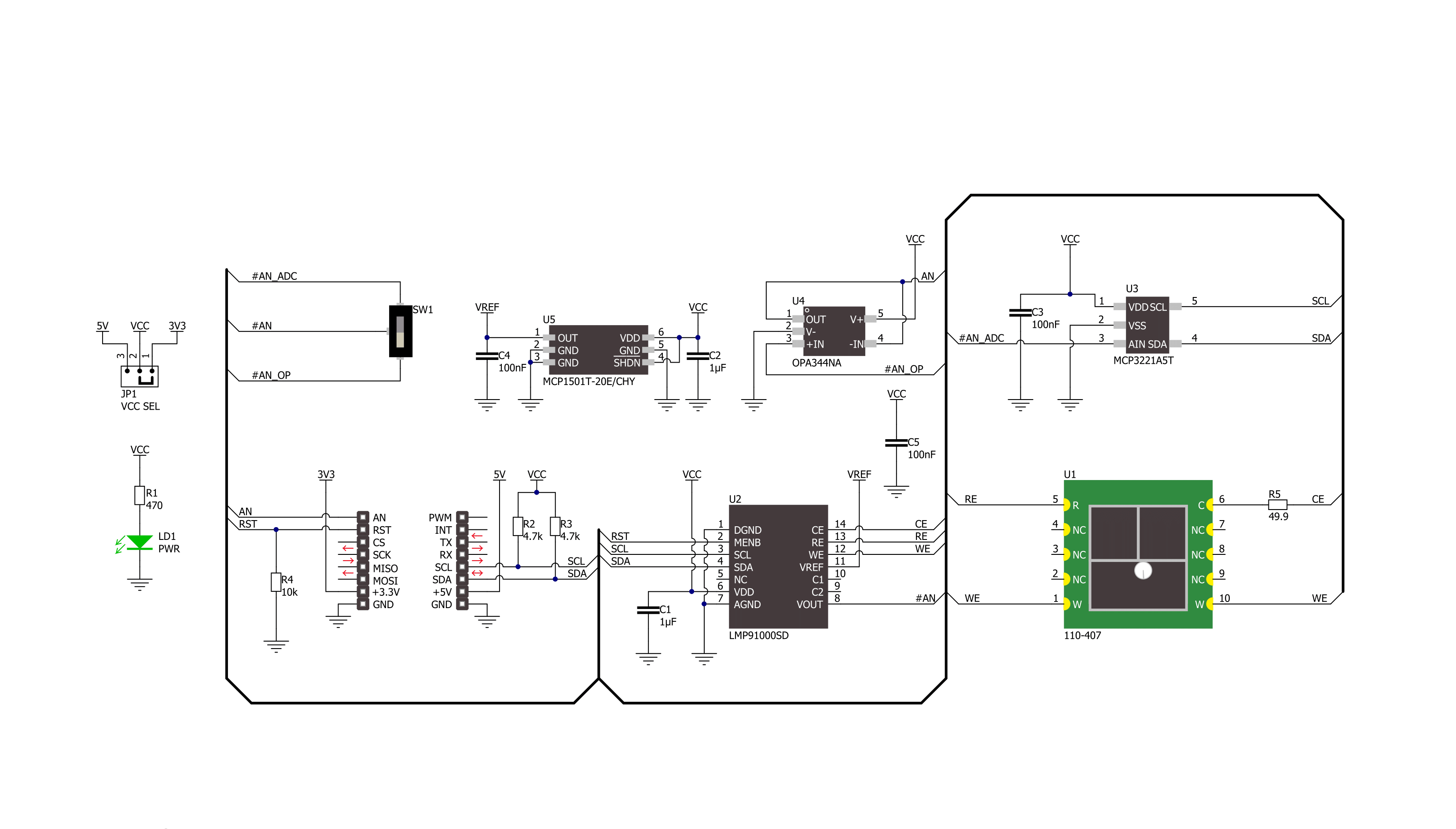
Ozone 3 Click is based on the 3SP-O3-20 (110-407), a high-performance ultra-thin electrochemical gas sensor that can sense ozone concentration up to 20ppm from SPEC Sensors. An electrochemical sensor like this one generates a current proportional to the volumetric fraction of the gas. This current is converted and transformed into the voltage by the analog front-end (AFE), so it can be sampled by the MCU or converted with the external A/D converting circuit. The sensor has very high sensitivity and short response time; however, the longer it is exposed to a particular gas, the more accurate data it can provide, especially true when calibration is performed. It is advised to protect the sensor when used in critical applications. In ideal conditions, the lifetime of this sensor is indefinite, but in real-life applications, the expected working life is more than five years (10 years at 23 ± 3 ˚C; 40 ± 10 %RH). Ozone 3 Click communicates with the MCU through the I2C serial interface using the LMP91000, a configurable
AFE IC for low-power chemical sensing applications from Texas Instruments that generates the output voltage proportional to the sensor current. The voltage between the referent electrode (RE) and the working electrode (WE) of the 110-407 is held constant, with the bias set by the variable bias circuitry. This type of sensor performs best when a fixed bias voltage is applied. Also, this Click board™ has two additional ICs onboard. The first one is the MCP3221, a 12-bit successive approximation register A/D converter from Microchip, and the second is the OPA344, a single supply, rail-to-rail operational amplifier from Texas Instruments. The RST pin of the mikroBUS™ socket, routed to the MEMB pin of the LMP91000, represents the enable feature of the I2C interface. When driven to a LOW logic level, the I2C communication is enabled, and the host MCU can issue a START condition. Note that the RST pin should stay at a LOW state during the communication. Besides that, it is possible to use
an onboard switch labeled as AN SEL to select the IC to which the VOUT pin from the LMP91000 AFE is routed. If the switch is in the position marked as ADC, the VOUT pin will be routed to the input of the MCP3221 ADC. This allows the voltage at the VOUT pin to be read via the I2C interface as digital information. When the switch is in the AN position, the VOUT pin of the LMP91000 is routed to the input of the OPA344. The output of the OPA344 Op-Amp has a stable unity gain, acting as a buffer so that the host MCU can sample the voltage at the VOUT pin of the AFE via the AN pin of the mikroBUS™ socket. This Click board™ can operate with either 3.3V or 5V logic voltage levels selected via the VCC SEL jumper. This way, both 3.3V and 5V capable MCUs can use the communication lines properly. Also, this Click board™ comes equipped with a library containing easy-to-use functions and an example code that can be used as a reference for further development.


Features overview
Development board
EasyPIC v8 for dsPIC30 is a development board specially designed for the needs of rapid development of embedded applications. It supports a wide range of 16-bit dsPIC30 microcontrollers from Microchip and has a broad set of unique functions, such as the first-ever embedded debugger/programmer. The development board is well organized and designed so that the end-user has all the necessary elements, such as switches, buttons, indicators, connectors, and others, in one place. Thanks to innovative manufacturing technology, EasyPIC v8 for dsPIC30 provides a fluid and immersive working experience, allowing access anywhere and under any circumstances.
Each part of the EasyPIC v8 for dsPIC30 development board contains the components necessary for the most efficient operation of the same board. In addition to the advanced integrated CODEGRIP programmer/debugger module, which offers many valuable programming/debugging options and seamless integration with the Mikroe software environment, the board also includes a clean and regulated power supply module for the development board. It can use a wide range of external power sources, including a battery, an external 12V power supply, and a power source via the USB Type-C (USB-C) connector. Communication options such as USB-UART, CAN,
and LIN are included, alongside the well-established mikroBUS™ standard, two display options (graphical and character-based LCD), and several different DIP sockets. These sockets cover a wide range of 16-bit dsPIC30 MCUs, from the smallest dsPIC30 MCUs with only 18 to 40 pins. EasyPIC v8 for dsPIC30 is an integral part of the Mikroe ecosystem for rapid development. Natively supported by Mikroe software tools, it covers many aspects of prototyping and development thanks to a considerable number of different Click boards™ (over a thousand boards), the number of which is growing every day.

Microcontroller Overview
MCU Card / MCU
Architecture
dsPIC
MCU Memory (KB)
48
Silicon Vendor
Microchip
Pin count
40
RAM (Bytes)
2048
Used MCU Pins
mikroBUS™ mapper
Take a closer look
Click board™ Schematic
Step by step
Project assembly

Start by selecting your development board and Click board™. Begin with the EasyPIC v8 for dsPIC30 as your development board.


Software Support
Library Description
This library contains API for Ozone 3 Click driver.
Key functions:
ozone3_read_adc- Ozone 3 read ADC functionozone3_get_o3_ppm- Ozone 3 get O3 ppm function
Open Source
Code example
The complete application code and a ready-to-use project are available through the NECTO Studio Package Manager for direct installation in the NECTO Studio. The application code can also be found on the MIKROE GitHub account.
/*!
 * @file main.c
 * @brief Ozone3 Click example
 *
 * # Description
 * This library contains API for the Ozone 3 Click driver.
 * This demo application shows an example of the O3 ppm data measurement.
 *
 * The demo application is composed of two sections :
 *
 * ## Application Init
 * Initialization of I2C module and log UART.
 * After driver initialization the app set default settings.
 *
 * ## Application Task
 * This is an example that shows the use of a Ozone 3 Click board™.
 * Get and logs O3 ( Trioxygen ) data as ppm value.
 * Results are being sent to the Usart Terminal where you can track their changes.
 *
 * @author Nenad Filipovic
 *
 */

#include "board.h"
#include "log.h"
#include "ozone3.h"

static ozone3_t ozone3;
static log_t logger;

void application_init ( void ) {
    log_cfg_t log_cfg;        /**< Logger config object. */
    ozone3_cfg_t ozone3_cfg;  /**< Click config object. */

    /**
     * Logger initialization.
     * Default baud rate: 115200
     * Default log level: LOG_LEVEL_DEBUG
     * @note If USB_UART_RX and USB_UART_TX
     * are defined as HAL_PIN_NC, you will
     * need to define them manually for log to work.
     * See @b LOG_MAP_USB_UART macro definition for detailed explanation.
     */
    LOG_MAP_USB_UART( log_cfg );
    log_init( &logger, &log_cfg );
    log_info( &logger, " Application Init " );

    // Click initialization.

    ozone3_cfg_setup( &ozone3_cfg );
    OZONE3_MAP_MIKROBUS( ozone3_cfg, MIKROBUS_1 );
    err_t init_flag = ozone3_init( &ozone3, &ozone3_cfg );
    if ( init_flag == I2C_MASTER_ERROR ) {
        log_error( &logger, " Application Init Error. " );
        log_info( &logger, " Please, run program again... " );

        for ( ; ; );
    }

    ozone3_default_cfg ( &ozone3 );
    log_info( &logger, " Application Task " );
    Delay_ms ( 300 );
}

void application_task ( void ) {
    float o3_ppm = ozone3_get_o3_ppm( &ozone3 );
    log_printf( &logger, "\tOzone : %.2f ppm \r\n", o3_ppm );
    Delay_ms ( 500 );
}

int main ( void )
{
    /* Do not remove this line or clock might not be set correctly. */
    #ifdef PREINIT_SUPPORTED
    preinit();
    #endif

    application_init( );

    for ( ; ; )
    {
        application_task( );
    }

    return 0;
}

// ------------------------------------------------------------------------ END
Additional Support
Resources
Category:Gas


