Enhance your thermal awareness with advanced thermal imaging solution based on the MLX90640-BAA and STM32G431RB
Count on clarity: The thermal imaging solution you need!
Published Nov 08, 2024
Click board™
IR Grid 3 click
Dev. board
Nucleo 64 with STM32G431RB MCU
Compiler
NECTO Studio
MCU
STM32G431RB
Elevate your thermal perception with our advanced thermal imaging solution, designed to enhance your ability to monitor, analyze, and optimize temperature-related aspects in your projects and processes
A
A
Hardware Overview
How does it work?
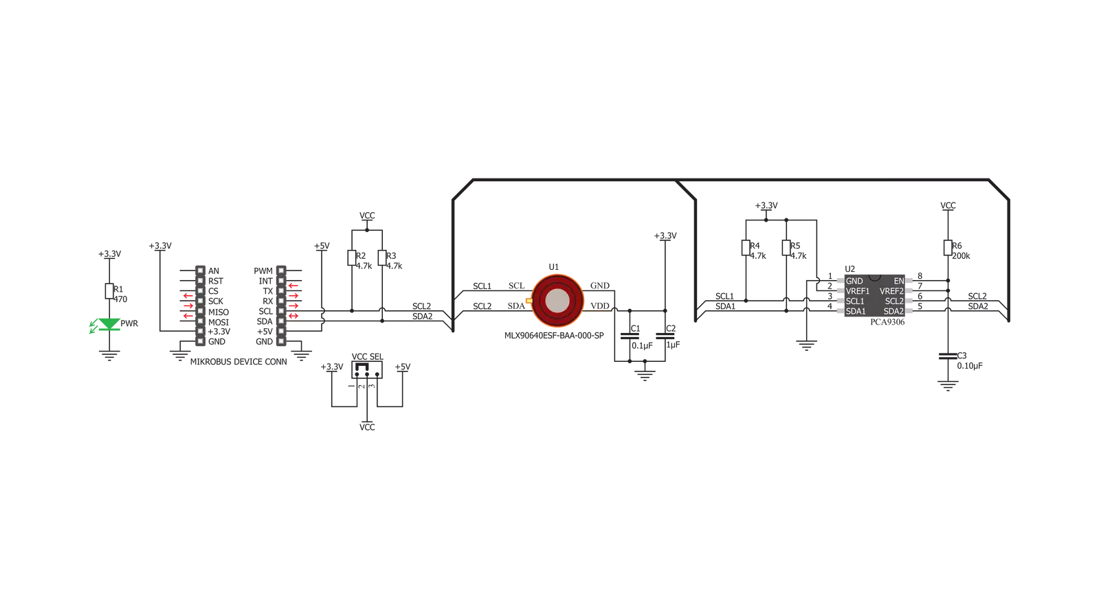
IR Grid 3 Click is based on the MLX90640ESF-BAA, a 32x24 IR array sensor, from Melexis. This sensor contains 8 Kbit EEPROM, used to store all the compensation and calibration parameters, along with some editable user parameters, such as the config registers, I2C address and similar. These sensors can measure temperature relative to the cold junction temperature, and for this reason, the MLX90640ESF-BAA IR sensor incorporates a PTAT (Proportional to Absolute Temperature) compensation sensor. The device also contains the power supply voltage measurement unit, allow power supply monitoring. It is recommended that the supply voltage stay as accurate as possible, which is taken care of if used with the MikroElektronika development systems. The IR sensor array, as well as the PTAT sensor readings, are sampled by fast internal ADC and stored on the RAM, which can be accessed via the I2C. The resolution of the ADC can be programmed between 16bit and 19bit. The MLX90640ESF-BAA IR sensor used on this Click board™ has a Field of View (FOV) of 110°x75°, with the IR sensing elements arranged in a 32x28 grid. Each sensor measures the temperature in its individual FOV, allowing the host MCU to build a thermal image or calculate the temperature at each spot of the viewed scene. The measurement results are stored in the onboard RAM. The entire RAM area is divided into two pages, with access patterns controlled by the configuration registers (chess
pattern, or interleaved pattern). The configuration parameters are factory calibrated for chess pattern access, yielding the most accurate results when using this mode. The chess pattern mode is selected by default. Two modes of operation are available: the device can continuously sample data from the IR elements, with the programmed refresh rate (up to 64 frames per second), or it can take one frame, by sampling the selected page. The status byte contains flags that indicate that the reading of a specific page is done. The configuration and control registers allow configuring of the working parameters. These registers contain bits that control the behavior of the sensor IC: the refresh rate, ADC resolution, measurement mode (continuous or step mode), sleep mode, I2C mode (FM or FM+), etc. The data from the EEPROM registers is copied after the POR cycle to the working RAM registers, preparing the device to be instantly operated. Besides the default working parameters, the EEPROM IC contains all the compensating parameters, necessary for completing the accurate thermal computations. A certain workflow has to be followed when operating this sensor. The workflow includes calculation of the compensation parameters that are stored in the EEPROM for each element. Those calculations include ambient temperature calculation, pixel offset calculation, pixel to pixel sensitivity difference compensation, object emissivity compensation, and object
temperature calculation. The datasheet of the MLX90640ESF-BAA IR sensor contains these equations, which use the parameters stored in EEPROM. However, this Click board™ is supported by the library, which contains functions that simplify working with this sensor. It should be noted that the sensor measures the IR emissivity of an object, so it is to expect that some materials cannot be accurately measured by this sensor due to their low emissivity, such as the aluminum. To better understand the emissivity property of the materials, a person wearing clothes, can be taken as an example: the measured temperature will reflect the clothes temperature, rather than the body temperature itself, which is known to be about 37 ˚C Care should be taken not to expose the Click board™ to a cold or hot air flow, as it will cause false readings of the real temperature. This sensor requires the temperature across the sensor package to be constant. The MLX90640ESF-BAA IR sensor uses 3.3V for optimal results. While the power for the IR sensor itself is taken from the 3.3V mikroBUS™ rail, in order to support MCUs which use 5V compatible logic levels, the Click board™ comes equipped with PCA9306, a bi-directional I2C level translator IC, produced by Texas Instruments. This allows the logic voltage level to be selected by the SMD jumper labeled as VCC SEL. Besides I2C bus lines, no additional lines of the mikroBUS™ are used. I2C bus lines are routed to the respective pins of the mikroBUS™.


Features overview
Development board
Nucleo-64 with STM32G431RB MCU offers a cost-effective and adaptable platform for developers to explore new ideas and prototype their designs. This board harnesses the versatility of the STM32 microcontroller, enabling users to select the optimal balance of performance and power consumption for their projects. It accommodates the STM32 microcontroller in the LQFP64 package and includes essential components such as a user LED, which doubles as an ARDUINO® signal, alongside user and reset push-buttons, and a 32.768kHz crystal oscillator for precise timing operations. Designed with expansion and flexibility in mind, the Nucleo-64 board features an ARDUINO® Uno V3 expansion connector and ST morpho extension pin
headers, granting complete access to the STM32's I/Os for comprehensive project integration. Power supply options are adaptable, supporting ST-LINK USB VBUS or external power sources, ensuring adaptability in various development environments. The board also has an on-board ST-LINK debugger/programmer with USB re-enumeration capability, simplifying the programming and debugging process. Moreover, the board is designed to simplify advanced development with its external SMPS for efficient Vcore logic supply, support for USB Device full speed or USB SNK/UFP full speed, and built-in cryptographic features, enhancing both the power efficiency and security of projects. Additional connectivity is
provided through dedicated connectors for external SMPS experimentation, a USB connector for the ST-LINK, and a MIPI® debug connector, expanding the possibilities for hardware interfacing and experimentation. Developers will find extensive support through comprehensive free software libraries and examples, courtesy of the STM32Cube MCU Package. This, combined with compatibility with a wide array of Integrated Development Environments (IDEs), including IAR Embedded Workbench®, MDK-ARM, and STM32CubeIDE, ensures a smooth and efficient development experience, allowing users to fully leverage the capabilities of the Nucleo-64 board in their projects.

Microcontroller Overview
MCU Card / MCU
Architecture
ARM Cortex-M4
MCU Memory (KB)
128
Silicon Vendor
STMicroelectronics
Pin count
64
RAM (Bytes)
32k
You complete me!
Accessories
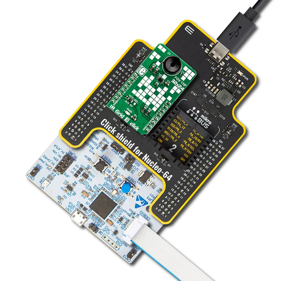
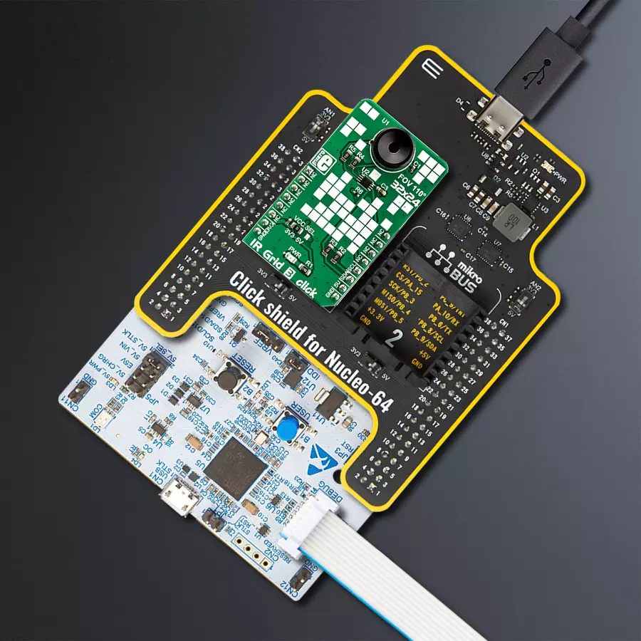
Click Shield for Nucleo-64 comes equipped with two proprietary mikroBUS™ sockets, allowing all the Click board™ devices to be interfaced with the STM32 Nucleo-64 board with no effort. This way, Mikroe allows its users to add any functionality from our ever-growing range of Click boards™, such as WiFi, GSM, GPS, Bluetooth, ZigBee, environmental sensors, LEDs, speech recognition, motor control, movement sensors, and many more. More than 1537 Click boards™, which can be stacked and integrated, are at your disposal. The STM32 Nucleo-64 boards are based on the microcontrollers in 64-pin packages, a 32-bit MCU with an ARM Cortex M4 processor operating at 84MHz, 512Kb Flash, and 96KB SRAM, divided into two regions where the top section represents the ST-Link/V2 debugger and programmer while the bottom section of the board is an actual development board. These boards are controlled and powered conveniently through a USB connection to program and efficiently debug the Nucleo-64 board out of the box, with an additional USB cable connected to the USB mini port on the board. Most of the STM32 microcontroller pins are brought to the IO pins on the left and right edge of the board, which are then connected to two existing mikroBUS™ sockets. This Click Shield also has several switches that perform functions such as selecting the logic levels of analog signals on mikroBUS™ sockets and selecting logic voltage levels of the mikroBUS™ sockets themselves. Besides, the user is offered the possibility of using any Click board™ with the help of existing bidirectional level-shifting voltage translators, regardless of whether the Click board™ operates at a 3.3V or 5V logic voltage level. Once you connect the STM32 Nucleo-64 board with our Click Shield for Nucleo-64, you can access hundreds of Click boards™, working with 3.3V or 5V logic voltage levels.

Used MCU Pins
mikroBUS™ mapper
Take a closer look
Click board™ Schematic
Step by step
Project assembly
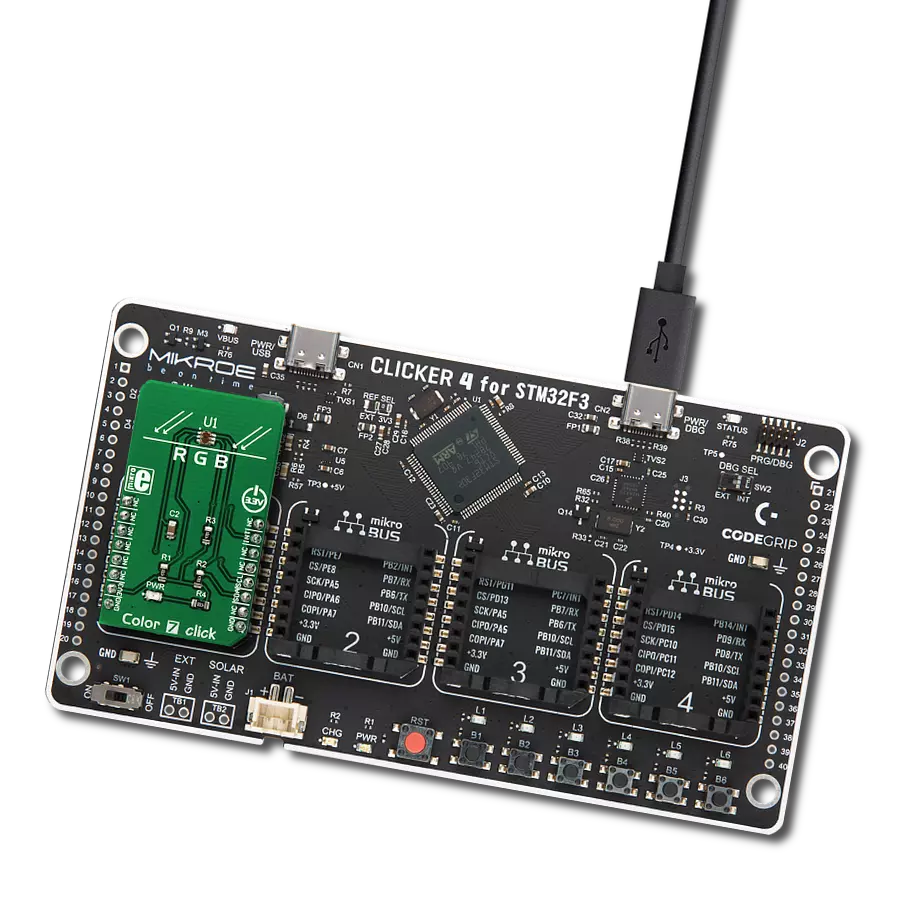
Start by selecting your development board and Click board™. Begin with the Nucleo 64 with STM32G431RB MCU as your development board.


Track your results in real time
Application Output
1. Application Output - In Debug mode, the 'Application Output' window enables real-time data monitoring, offering direct insight into execution results. Ensure proper data display by configuring the environment correctly using the provided tutorial.

2. UART Terminal - Use the UART Terminal to monitor data transmission via a USB to UART converter, allowing direct communication between the Click board™ and your development system. Configure the baud rate and other serial settings according to your project's requirements to ensure proper functionality. For step-by-step setup instructions, refer to the provided tutorial.

3. Plot Output - The Plot feature offers a powerful way to visualize real-time sensor data, enabling trend analysis, debugging, and comparison of multiple data points. To set it up correctly, follow the provided tutorial, which includes a step-by-step example of using the Plot feature to display Click board™ readings. To use the Plot feature in your code, use the function: plot(*insert_graph_name*, variable_name);. This is a general format, and it is up to the user to replace 'insert_graph_name' with the actual graph name and 'variable_name' with the parameter to be displayed.

Software Support
Library Description
This library contains API for IR Grid 3 Click driver.
Key functions:
irgrid3_generic_write- This function reads a desired number of data bytes starting from the selected register by using I2C serial interfaceirgrid3_get_frame_data- This function is used for getting frame datairgrid3_get_pixel_temperature- This function is used for getting pixels temperature.
Open Source
Code example
The complete application code and a ready-to-use project are available through the NECTO Studio Package Manager for direct installation in the NECTO Studio. The application code can also be found on the MIKROE GitHub account.
/*!
 * @file main.c
 * @brief IRGrid3 Click example
 *
 * # Description
 * The demo application displays a reading of ambient temperature and
 * a 32x24 pixel object temperature matrix.
 *
 * The demo application is composed of two sections :
 *
 * ## Application Init
 * Configures the Click and log objects and sets the Click default configuration.
 *
 * ## Application Task
 * Reads the temperature of all pixels every 500ms
 * and displays it on USB UART in a form of a 32x24 matrix.
 *
 * @author Stefan Ilic
 *
 */

#include "board.h"
#include "log.h"
#include "irgrid3.h"

static irgrid3_t irgrid3;
static log_t logger;

void application_init ( void ) {
    log_cfg_t log_cfg;  /**< Logger config object. */
    irgrid3_cfg_t irgrid3_cfg;  /**< Click config object. */

    /**
     * Logger initialization.
     * Default baud rate: 115200
     * Default log level: LOG_LEVEL_DEBUG
     * @note If USB_UART_RX and USB_UART_TX
     * are defined as HAL_PIN_NC, you will
     * need to define them manually for log to work.
     * See @b LOG_MAP_USB_UART macro definition for detailed explanation.
     */
    LOG_MAP_USB_UART( log_cfg );
    log_init( &logger, &log_cfg );
    log_info( &logger, "---- Application Init ----" );

    // Click initialization.
    irgrid3_cfg_setup( &irgrid3_cfg );
    IRGRID3_MAP_MIKROBUS( irgrid3_cfg, MIKROBUS_1 );
    err_t init_flag = irgrid3_init( &irgrid3, &irgrid3_cfg );
    if ( I2C_MASTER_ERROR == init_flag ) {
        log_error( &logger, " Application Init Error. " );
        log_info( &logger, " Please, run program again... " );

        for ( ; ; );
    }

    irgrid3_default_cfg ( &irgrid3 );
    Delay_ms ( 1000 );
    log_info( &logger, "---- Start measurement ----" );
}

void application_task ( void ) {
    float px_matrix[ 768 ];
    float temp_ambient;

    irgrid3_get_pixel_temperature( &irgrid3, &temp_ambient, px_matrix );

    log_printf( &logger, "\r\n>> Pixel temperature matrix 32x24 <<\r\n" );
    for ( uint16_t cnt = 1 ; cnt < 769 ; cnt++) {
        log_printf( &logger, "%.2f", px_matrix[ cnt - 1 ] );
        if ( ( ( cnt % 32 ) == 0 ) ) {
            log_printf( &logger, "\r\n" );
        } else {
            log_printf( &logger, " | " );
        }
    }
    log_printf( &logger, "\r\n** Ambient (sensor) temperature is %.2f Celsius\r\n", temp_ambient );
    Delay_ms ( 500 );
}

int main ( void )
{
    /* Do not remove this line or clock might not be set correctly. */
    #ifdef PREINIT_SUPPORTED
    preinit();
    #endif

    application_init( );

    for ( ; ; )
    {
        application_task( );
    }

    return 0;
}

// ------------------------------------------------------------------------ END