Experience the convenience of wireless networking with ATWINC3400-MR210CA and PIC32MX795F512L
Our WiFi solution, your digital oasis!

Published Jul 29, 2023
Click board™
WiFi 8 Click
Dev. board
EasyPIC Fusion v7
Compiler
NECTO Studio
MCU
PIC32MX795F512L
With our WiFi solution, you can enjoy the freedom of an untethered connection, empowering you to work, play, and connect without boundaries
A
A
Hardware Overview
How does it work?
WiFi 8 Click is based on the ATWINC3400-MR210CA, an RF/Baseband/Medium Access Control (MAC) network controller (Bluetooth 5.0 certified module) optimized for low-power and high-performance mobile applications from Microchip Technology. The ATWINC3400-MR210CA supports the simultaneous use of Bluetooth Low Energy and WiFi via a coexistence mechanism, allowing them to share the same radio. The radio defaults to WiFi use until a Bluetooth Low Energy event occurs, in which case the radio is switched over for Bluetooth Low Energy use. It comes with integrated power and low-noise amplifiers, transmit/receive switch (for WiFi and Bluetooth), a power management unit, an integrated 2.4GHz chip antenna, and an additional 32.768 kHz clock to supply the module during Sleep mode. The ATWINC3400-MR210CA module has multiple device states (WiFi TX/RX, BLE TX/RX, Doze, and Power-Down Mode) based on the state of the IEEE 802.11 and Bluetooth subsystems with
the possibility for both subsystems to be active at the same time. It has two Cortus APS3 32-bit processors, one for WiFi and the other for Bluetooth. The APS3 core uses a 256KB instruction/boot ROM, 420KB instruction RAM, and 128KB data RAM. In addition, the module uses a 160KB shared/exchange RAM accessible by the processor and MAC, which allows the processor to perform various data management tasks on the TX and RX data packets. WiFi 8 Click communicates with MCU using the SPI serial interface with a maximum clock frequency of 48MHz applicable to all SPI modes. Additional functionality, such as the Chip Enable, is used to Enable or put the module in Shut-Down mode provided and routed at the EN pin of the mikroBUS™ socket. Alongside this pin, this Click board™ has a Reset button routed to the RST pin on the mikroBUS™ socket, which with a low logic level, puts the module into a Reset state and, with a high level, operates the module normally.
This Click board™ also has several additional headers suitable for debugging using the UART and I2C interfaces labeled DBG UART and DBG I2C. It also has a header marked GPIO with all general-purpose pins from the ATWINC3400-MR210CA module. It should be noted that the GPIO functionality is currently not supported by the ATWINC3400 firmware. Besides, it also has two additional LED indicators, red and yellow LEDs labeled STAT1 and STAT2, which can be used for optional user-configurable visual indication. This Click board™ can be operated only with a 3.3V logic voltage level. The board must perform appropriate logic voltage level conversion before using MCUs with different logic levels. Also, it comes equipped with a library containing functions and an example code that can be used, as a reference, for further development.

Features overview
Development board
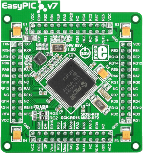
EasyPIC Fusion v7 is the seventh generation of PIC development boards specially designed to develop embedded applications rapidly. It supports a wide range of 16/32-bit PIC microcontrollers from Microchip and a broad set of unique functions, such as a powerful onboard mikroProg programmer and In-Circuit debugger over USB-B. The development board is well organized and designed so that the end-user has all the necessary elements, such as switches, buttons, indicators, connectors, and others, in one place. With two different connectors for each port, EasyPIC Fusion v7 allows you to connect accessory boards, sensors, and custom electronics more efficiently than ever. Each part of
the EasyPIC Fusion v7 development board contains the components necessary for the most efficient operation of the same board. An integrated mikroProg, a fast USB 2.0 programmer with mikroICD hardware In-Circuit Debugger, offers many valuable programming/debugging options and seamless integration with the Mikroe software environment. Besides it also includes a clean and regulated power supply block for the development board. It can use a wide range of external power sources, including an external 12V power supply, 7-12V AC or 9-15V DC via DC connector/screw terminals, and a power source via the USB Type-B (USB-B) connector. Communication options such
as USB-UART, USB-HOST, CAN, and Ethernet are also included, including the well-established mikroBUS™ standard, one display option for the TFT board line of products, and a standard TQFP socket for the seventh-generation MCU cards. This socket covers a wide range of 16-bit dsPIC/PIC24 and 32-bit PIC32 MCUs. EasyPIC Fusion v7 is an integral part of the Mikroe ecosystem for rapid development. Natively supported by Mikroe software tools, it covers many aspects of prototyping and development thanks to a considerable number of different Click boards™ (over a thousand boards), the number of which is growing every day.

Microcontroller Overview
MCU Card / MCU
Type
7th Generation
Architecture
PIC32
MCU Memory (KB)
512
Silicon Vendor
Microchip
Pin count
100
RAM (Bytes)
131072
Used MCU Pins
mikroBUS™ mapper
Take a closer look
Click board™ Schematic

Step by step
Project assembly

Start by selecting your development board and Click board™. Begin with the EasyPIC Fusion v7 as your development board.


Track your results in real time
Application Output
1. Application Output - In Debug mode, the 'Application Output' window enables real-time data monitoring, offering direct insight into execution results. Ensure proper data display by configuring the environment correctly using the provided tutorial.

2. UART Terminal - Use the UART Terminal to monitor data transmission via a USB to UART converter, allowing direct communication between the Click board™ and your development system. Configure the baud rate and other serial settings according to your project's requirements to ensure proper functionality. For step-by-step setup instructions, refer to the provided tutorial.

3. Plot Output - The Plot feature offers a powerful way to visualize real-time sensor data, enabling trend analysis, debugging, and comparison of multiple data points. To set it up correctly, follow the provided tutorial, which includes a step-by-step example of using the Plot feature to display Click board™ readings. To use the Plot feature in your code, use the function: plot(*insert_graph_name*, variable_name);. This is a general format, and it is up to the user to replace 'insert_graph_name' with the actual graph name and 'variable_name' with the parameter to be displayed.

Software Support
Library Description
This library contains API for WiFi 8 Click driver.
Key functions:
wifi8_init_drv- Synchronous API to initialize the device driverwifi8_connect- Asynchronous Wi-Fi connection functionwifi8_socket_bind- Asynchronous bind function associates the provided address and local port to the socket
Open Source
Code example
The complete application code and a ready-to-use project are available through the NECTO Studio Package Manager for direct installation in the NECTO Studio. The application code can also be found on the MIKROE GitHub account.
/*!
 * @file main.c
 * @brief WiFi8 Click example
 *
 * # Description
 * This application showcases capability of the WiFi 8 Click board.
 * It initializes device, connects to local WiFi. Creates TCP, waits for connection
 * and logs every message it receives for clients when it receives CR or LF flag
 * it returns message back to Client.
 *
 * The demo application is composed of two sections :
 *
 * ## Application Init
 * Initializes Host logger, and communication module and pins.
 * Then resets device and initializes devices firmware. If no error
 * occurred it sets callback functions for WiFi and TCP socket, and checks
 * current firmware version. After firmware is read it connects to local WiFi network
 * set by user. When connected it initializes and creates socket.
 *
 * ## Application Task
 * It loops function for handling events. Should notify and log messages when Client
 * is connected/disconnected to TCP server and returns back when receives CR or LF flag.
 *
 * @note
 * User should set @b MAIN_WLAN_SSID and @b MAIN_WLAN_PSK for connecting to local network.
 * When devices connects to network it will log its IP that user need to connect to.
 * After user connects it should get notification and it can send data to server.
 * Server will return message "WiFi 8 Click" when Client sends CR or LF character in message.
 *
 * @author Luka Filipovic
 *
 */

#include "board.h"
#include "log.h"
#include "wifi8.h"

static wifi8_t wifi8;
static log_t logger;

/** Wi-Fi Settings */
#define MAIN_WLAN_SSID      "MikroE Public"         /**< Destination SSID */
#define MAIN_WLAN_AUTH       M2M_WIFI_SEC_WPA_PSK   /**< Security type */
#define MAIN_WLAN_PSK        "mikroe.guest"         /**< Password for Destination SSID */
#define MAIN_TCP_SERVER_PORT 8080                   /**< TCP Server port for client connection */

typedef struct s_msg_wifi_product
{
    uint8_t name[30];

} t_msg_wifi_product;

static t_msg_wifi_product msg_wifi_product =
{
    .name = "WiFi 8 Click"
};

static uint8_t gau8_socket_test_buffer[1024] = {0};

static int8_t tcp_server_socket = -1;
static int8_t tcp_client_socket = -1;
wifi8_sockaddr_in_t addr;

static uint8_t wifi_connected;

static uint8_t scan_request_index = 0;

static uint8_t num_found_ap = 0;

static void wifi_cb(uint8_t u8_msg_type, void *pv_msg);

static void socket_cb(int8_t sock, uint8_t u8_msg, void *pv_msg);

void application_init(void)
{
    log_cfg_t log_cfg;
    wifi8_cfg_t wifi8_cfg;

    /**
     * Logger initialization.
     * Default baud rate: 115200
     * Default log level: LOG_LEVEL_DEBUG
     * @note If USB_UART_RX and USB_UART_TX
     * are defined as HAL_PIN_NC, you will
     * need to define them manually for log to work.
     * See @b LOG_MAP_USB_UART macro definition for detailed explanation.
     */
    LOG_MAP_USB_UART( log_cfg );
    log_init( &logger, &log_cfg );
    log_info(&logger, " Application Init ");

    Delay_ms ( 1000 );

    wifi8_cfg_setup(&wifi8_cfg);
    WIFI8_MAP_MIKROBUS(wifi8_cfg, MIKROBUS_1);
    err_t init_flag = wifi8_init(&wifi8, &wifi8_cfg);
    if (init_flag == SPI_MASTER_ERROR)
    {
        log_error(&logger, " Application Init Error. ");
        log_info(&logger, " Please, run program again... ");
        for (;;);
    }

    if (WIFI8_OK != wifi8_default_cfg(&wifi8))
    {
        log_error(&logger, " Default configuartion. ");
        for (;;);
    }
    //Set callback functions for WiFi and TCP socket
    wifi8.app_wifi_cb = wifi_cb;
    wifi8.app_socket_cb = socket_cb;
    wifi_connected = M2M_WIFI_DISCONNECTED;

    wifi8_m2m_rev_t fw_version;
    if (WIFI8_OK == wifi8_get_full_firmware_version(&wifi8, &fw_version))
    {
        log_printf(&logger, "Firmware HIF (%u) : %u.%u \n",
                   ((uint16_t)(((fw_version.u16_firmware_hif_info) >> (14)) & (0x3))),
                   ((uint16_t)(((fw_version.u16_firmware_hif_info) >> (8)) & (0x3f))),
                   ((uint16_t)(((fw_version.u16_firmware_hif_info) >> (0)) & (0xff))));
        log_printf(&logger, "Firmware ver   : %u.%u.%u \n",
                   (uint16_t)fw_version.u8_firmware_major,
                   (uint16_t)fw_version.u8_firmware_minor,
                   (uint16_t)fw_version.u8_firmware_patch);
        log_printf(&logger, "Firmware Build %s Time %s\n", fw_version.build_date, fw_version.build_time);
    }
    else
    {
        log_error(&logger, " reading full firmware version ");
        for (;;);
    }

    if (wifi_connected == M2M_WIFI_DISCONNECTED)
    {
        if (WIFI8_OK != wifi8_connect(&wifi8, MAIN_WLAN_SSID, sizeof(MAIN_WLAN_SSID),
                                      MAIN_WLAN_AUTH, MAIN_WLAN_PSK, M2M_WIFI_CH_ALL))
        {
            log_error(&logger, " Connection");
            for (;;);
        }
        else
        {
            log_info(&logger, " Connecting... ");
        }
    }

    while (wifi_connected != M2M_WIFI_CONNECTED)
    {
        wifi8_handle_events(&wifi8);
    }

    wifi8_socket_init(&wifi8);
    addr.sin_family = 2;
    addr.sin_port = (uint16_t)((((uint16_t)((MAIN_TCP_SERVER_PORT))) << 8) | (((uint16_t)((MAIN_TCP_SERVER_PORT))) >> 8));
    addr.sin_addr.s_addr = 0;

    log_info(&logger, " Application Task ");
}

void application_task(void)
{
    wifi8_handle_events(&wifi8);

    if (tcp_server_socket < 0)
    {

        if ((tcp_server_socket = wifi8_socket_create(&wifi8, 2, 1, 0)) < 0)
        {
            log_printf(&logger, "main: failed to create TCP server socket error!\r\n");
        }
        else
        {
            wifi8_socket_bind(&wifi8, tcp_server_socket, (wifi8_sockaddr_t *)&addr,
                              sizeof(wifi8_sockaddr_in_t));
        }
    }
}

int main ( void )
{
    /* Do not remove this line or clock might not be set correctly. */
    #ifdef PREINIT_SUPPORTED
    preinit();
    #endif

    application_init( );

    for ( ; ; )
    {
        application_task( );
    }

    return 0;
}

static void wifi_cb(uint8_t u8_msg_type, void *pv_msg)
{
    switch (u8_msg_type)
    {
        case M2M_WIFI_RESP_SCAN_DONE:
        {
            wifi8_m2m_scan_done_t *pstr_info = (wifi8_m2m_scan_done_t *)pv_msg;
            scan_request_index = 0;
            if (pstr_info->u8_numof_ch >= 1)
            {
                wifi8_req_scan_result(&wifi8, scan_request_index);
                scan_request_index++;
            }
            else
            {
                wifi8_request_scan(&wifi8, M2M_WIFI_CH_ALL);
            }

            break;
        }
        case M2M_WIFI_RESP_SCAN_RESULT:
        {
            wifi8_m2m_wifiscan_result_t *pstr_scan_result = (wifi8_m2m_wifiscan_result_t *)pv_msg;
            uint16_t demo_ssid_len;
            uint16_t scan_ssid_len = strlen((char *)pstr_scan_result->au8ssid);

            log_printf(&logger, "wifi_cb: [%d] SSID:%s\r\n", (uint16_t)scan_request_index, pstr_scan_result->au8ssid);

            num_found_ap = wifi8.ch_num;
            if (scan_ssid_len)
            {
                demo_ssid_len = strlen((const char *)MAIN_WLAN_SSID);
                if ((demo_ssid_len == scan_ssid_len) &&
                    (!memcmp(pstr_scan_result->au8ssid, (uint8_t *)MAIN_WLAN_SSID, demo_ssid_len)))
                {
                    log_printf(&logger, "wifi_cb: found %s \r\n", MAIN_WLAN_SSID);
                    wifi8_connect(&wifi8, MAIN_WLAN_SSID, sizeof(MAIN_WLAN_SSID),
                                M2M_WIFI_SEC_WPA_PSK, MAIN_WLAN_PSK, M2M_WIFI_CH_ALL);
                    break;
                }
            }

            if (scan_request_index < num_found_ap)
            {
                wifi8_req_scan_result(&wifi8, scan_request_index);
                scan_request_index++;
            }
            else
            {
                log_printf(&logger, "wifi_cb: can not find AP %s\r\n", MAIN_WLAN_SSID);
                wifi8_request_scan(&wifi8, M2M_WIFI_CH_ALL);
            }

            break;
        }
        case M2M_WIFI_RESP_CON_STATE_CHANGED:
        {
            wifi8_m2m_wifi_state_changed_t *pstr_wifi_state = (wifi8_m2m_wifi_state_changed_t *)pv_msg;
            if (pstr_wifi_state->u8_curr_state == M2M_WIFI_CONNECTED)
            {
                log_printf(&logger, "wifi_cb: connected\r\n");
            }
            else if (pstr_wifi_state->u8_curr_state == M2M_WIFI_DISCONNECTED)
            {
                log_printf(&logger, "wifi_cb: disconnected\r\n");
                wifi_connected = M2M_WIFI_DISCONNECTED;

                wifi8_request_scan(&wifi8, M2M_WIFI_CH_ALL);
            }

            break;
        }
        case M2M_WIFI_REQ_DHCP_CONF:
        {
            volatile uint8_t *pu8ip_address = (uint8_t *)pv_msg;

            log_printf(&logger, "wifi_cb: IP: %u.%u.%u.%u\r\n",
                    (uint16_t)pu8ip_address[0], (uint16_t)pu8ip_address[1],
                    (uint16_t)pu8ip_address[2], (uint16_t)pu8ip_address[3]);

            wifi_connected = M2M_WIFI_CONNECTED;
            break;
        }
        default:
        {
            break;
        }
    }
}

static void socket_cb(int8_t sock, uint8_t u8_msg, void *pv_msg)
{
    switch (u8_msg)
    {
        case SOCKET_MSG_BIND:
        {
            wifi8_socket_bind_msg_t *pstr_bind = (wifi8_socket_bind_msg_t *)pv_msg;
            if (pstr_bind && pstr_bind->status == 0)
            {
                log_printf(&logger, "socket_cb: bind success!\r\n");
                Delay_ms ( 500 );
                wifi8_socket_listen(&wifi8, tcp_server_socket, 0);
            }
            else
            {
                log_printf(&logger, "socket_cb: bind error!\r\n");
                wifi8_socket_close(&wifi8, tcp_server_socket);
                tcp_server_socket = -1;
            }
        }
        break;
        case SOCKET_MSG_LISTEN:
        {
            wifi8_socket_listen_msg_t *pstr_listen = (wifi8_socket_listen_msg_t *)pv_msg;
            if (pstr_listen && pstr_listen->status == 0)
            {
                log_printf(&logger, "socket_cb: listen success!\r\n");
            }
            else
            {
                log_printf(&logger, "socket_cb: listen error!\r\n");
                wifi8_socket_close(&wifi8, tcp_server_socket);
                tcp_server_socket = -1;
            }
        }
        break;
        case SOCKET_MSG_ACCEPT:
        {
            wifi8_socket_accept_msg_t *pstr_accept = (wifi8_socket_accept_msg_t *)pv_msg;
            if (pstr_accept)
            {
                log_printf(&logger, "socket_cb: accept success!\r\n");
                tcp_client_socket = pstr_accept->sock;
                wifi8_socket_receive(&wifi8, tcp_client_socket, gau8_socket_test_buffer, sizeof(gau8_socket_test_buffer), 0);
            }
            else
            {
                log_printf(&logger, "socket_cb: accept error!\r\n");
                wifi8_socket_close(&wifi8, tcp_server_socket);
                tcp_server_socket = -1;
            }
        }
        break;
        case SOCKET_MSG_SEND:
        {
            log_printf(&logger, "socket_cb: send success!\r\n");
            wifi8_socket_receive(&wifi8, tcp_client_socket, gau8_socket_test_buffer, sizeof(gau8_socket_test_buffer), 0);
        }
        break;
        case SOCKET_MSG_RECV:
        {
            wifi8_socket_recv_msg_t *pstr_recv = (wifi8_socket_recv_msg_t *)pv_msg;
            if (pstr_recv && pstr_recv->s16_buffer_size > 0)
            {
                log_printf(&logger, "%s", pstr_recv->pu8_buffer);
                if ((strchr(pstr_recv->pu8_buffer, 13) != 0) || (strchr(pstr_recv->pu8_buffer, 10) != 0))
                {
                    wifi8_socket_send(&wifi8, tcp_client_socket, &msg_wifi_product, sizeof(t_msg_wifi_product));
                }
                else
                {
                    wifi8_socket_receive(&wifi8, tcp_client_socket, gau8_socket_test_buffer, sizeof(gau8_socket_test_buffer), 0);
                }
                memset(pstr_recv->pu8_buffer, 0, pstr_recv->s16_buffer_size);
            }
            else
            {
                log_printf(&logger, "socket_cb: close socket!\r\n");
                wifi8_socket_close(&wifi8, tcp_server_socket);
                tcp_server_socket = -1;
            }
        }
        break;
        default:
        {
            break;
        }
    }
}

// ------------------------------------------------------------------------ END