Establish a wireless data link to a GSM/GPSR network with SARA-G450 and STM32F207ZG
Cellular IoT connectivity

Published Mar 11, 2023
Click board™
GSM 5 Click
Dev Board
UNI-DS v8
Compiler
NECTO Studio
MCU
STM32F207ZG
Quad-band GSM/GPRS voice and data transmission technology in a compact form factor
A
A
Hardware Overview
How does it work?
GSM 5 Click is based on the SARA-G450, a compact quad-band 2.5G GSM/GPRS module from u-blox. Alongside low power consumption, the SARA-G450 module also features a baseband, RF transceiver, power management unit, and power amplifier in a single solution, supporting 2G, 3G, LTE, and LPWA (Cat M1 and Cat NB1) radio access technologies. Covering 850/900MHz and 1800/1900MHz bands, it provides a fully qualified and certified solution, reducing cost and enabling a short time to market. It is ideally suited for M2M applications such as automatic meter reading, remote monitoring automation and control, surveillance, security, asset tracking, and more. This module has comprehensive features, including an extensive set of internet protocols. It is also designed to provide fully integrated access to u-blox GNSS positioning with embedded A-GPS (AssistNow Online and AssistNow Offline) functionality. Any host processor connected to the cellular module
through a single serial port can control the module and GNSS positioning. The SARA-G450 module also offers extensive audio features, which users can access via an onboard 3.5mm audio jack, all configurable through the AT commands. This Click board™ communicates with MCU using the UART interface with commonly used UART RX, TX, and hardware flow control pins UART CTS, RTS, and RI (Clear to Send, Ready to Send, and Ring Indicator) by exchanging standard AT commands. It operates at 115200 bps by default to transmit and exchange data with the host MCU. An additional interface can also be found on the board as a test point for firmware upgrades and trace log capture (for diagnostics purposes). In addition to the UART, this Click board™ also has two additional ON/OFF pins used to turn ON/OFF the chip itself. Besides, it uses two orange LED indicators labeled GP1 and GP2 for optional user-configurable network-status visual indications such as registered home network,
registered roaming, voice or data call enabled, and no service. GSM 5 Click possesses the SMA antenna connector on which an appropriate antenna connects that Mikroe has in its offer. It also has a USB type C connector and a Nano-SIM card slot that provides multiple connections and interface options. USB allows the module to be powered and configured by a personal computer (PC) using FT230X, a compact USB to a serial UART interface bridge. This Click board™ can operate with both 3.3V and 5V MCUs. Appropriate voltage level translators perform a proper logic voltage level conversion, while the onboard LDO, the TPS7A7002, ensures the recommended voltage levels power module. However, the Click board™ comes equipped with a library containing easy-to-use functions and an example code that can be used, as a reference, for further development.

Features overview
Development board
UNI-DS v8 is a development board specially designed for the needs of rapid development of embedded applications. It supports a wide range of microcontrollers, such as different STM32, Kinetis, TIVA, CEC, MSP, PIC, dsPIC, PIC32, and AVR MCUs regardless of their number of pins, and a broad set of unique functions, such as the first-ever embedded debugger/programmer over WiFi. The development board is well organized and designed so that the end-user has all the necessary elements, such as switches, buttons, indicators, connectors, and others, in one place. Thanks to innovative manufacturing technology, UNI-DS v8 provides a fluid and immersive working experience, allowing access anywhere and under any
circumstances at any time. Each part of the UNI-DS v8 development board contains the components necessary for the most efficient operation of the same board. An advanced integrated CODEGRIP programmer/debugger module offers many valuable programming/debugging options, including support for JTAG, SWD, and SWO Trace (Single Wire Output)), and seamless integration with the Mikroe software environment. Besides, it also includes a clean and regulated power supply module for the development board. It can use a wide range of external power sources, including a battery, an external 12V power supply, and a power source via the USB Type-C (USB-C) connector. Communication options such as USB-UART, USB
HOST/DEVICE, CAN (on the MCU card, if supported), and Ethernet is also included. In addition, it also has the well-established mikroBUS™ standard, a standardized socket for the MCU card (SiBRAIN standard), and two display options for the TFT board line of products and character-based LCD. UNI-DS v8 is an integral part of the Mikroe ecosystem for rapid development. Natively supported by Mikroe software tools, it covers many aspects of prototyping and development thanks to a considerable number of different Click boards™ (over a thousand boards), the number of which is growing every day.

Microcontroller Overview
MCU Card / MCU
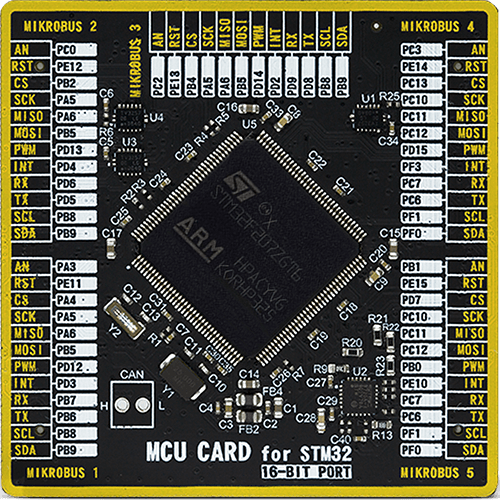
Type
8th Generation
Architecture
ARM Cortex-M3
MCU Memory (KB)
1024
Silicon Vendor
STMicroelectronics
Pin count
144
RAM (Bytes)
131072
You complete me!
Accessories
The GSM right-angle rubber antenna is a perfect match for our GSM Click boards™. With a wide bandwidth accommodating GSM/GPRS modules, this antenna has a 2m cable featuring an SMA male connector for easy positioning. Operating within a frequency range of 824-894/1710-1990MHz or 890-960/1710-1890MHz, it maintains a 50Ohm impedance, delivering a gain of 3dB. Its 90/280MHz bandwidth ensures reliable connectivity, while its vertical polarization optimizes signal reception. With a maximum input power of 60W, it offers robust performance. Measuring just 90mm in length, this magnetic antenna is compact yet powerful. Its SMA male connector ensures a secure and stable connection, making it an ideal choice for seamless integration with any GSM Click board™.

Used MCU Pins
mikroBUS™ mapper
Take a closer look
Schematic

Step by step
Project assembly

Start by selecting your development board and Click board™. Begin with the UNI-DS v8 as your development board.


Track your results in real time
Application Output
After pressing the "FLASH" button on the left-side panel, it is necessary to open the UART terminal to display the achieved results. By clicking on the Tools icon in the right-hand panel, multiple different functions are displayed, among which is the UART Terminal. Click on the offered "UART Terminal" icon.

Once the UART terminal is opened, the window takes on a new form. At the top of the tab are two buttons, one for adjusting the parameters of the UART terminal and the other for connecting the UART terminal. The tab's lower part is reserved for displaying the achieved results. Before connecting, the terminal has a Disconnected status, indicating that the terminal is not yet active. Before connecting, it is necessary to check the set parameters of the UART terminal. Click on the "OPTIONS" button.

In the newly opened UART Terminal Options field, we check if the terminal settings are correct, such as the set port and the Baud rate of UART communication. If the data is not displayed properly, it is possible that the Baud rate value is not set correctly and needs to be adjusted to 115200. If all the parameters are set correctly, click on "CONFIGURE".

The next step is to click on the "CONNECT" button, after which the terminal status changes from Disconnected to Connected in green, and the data is displayed in the Received data field.

Software Support
Library Description
This library contains API for GSM 5 Click driver.
Key functions:
gsm5_send_cmdThis function sends a specified command to the click module.gsm5_set_sim_apnThis function sets APN for sim card.gsm5_send_sms_textThis function sends text message to a phone number.
Open Source
Code example
This example can be found in NECTO Studio. Feel free to download the code, or you can copy the code below.
/*!
 * @file main.c
 * @brief GSM 5 Click Example.
 *
 * # Description
 * Application example shows device capability of connecting to the network and
 * sending SMS or TCP/UDP messages using standard "AT" commands.
 *
 * The demo application is composed of two sections :
 *
 * ## Application Init
 * Initializes the driver, wakes the module up and tests the communication.
 *
 * ## Application Task
 * Application task is split in few stages:
 *  - GSM5_CONFIGURE_FOR_NETWORK:
 * Sets configuration to device to be able to connect to the network.
 *
 *  - GSM5_WAIT_FOR_CONNECTION:
 * Waits for the network registration indicated via CREG URC event and then checks
 * the connection status.
 *
 *  - GSM5_CONFIGURE_FOR_EXAMPLE:
 * Sets the device configuration for sending SMS or TCP/UDP messages depending on the
 * selected demo example.
 *
 *  - GSM5_EXAMPLE:
 * Depending on the selected demo example, it sends an SMS message (in PDU or TXT mode) or
 * TCP/UDP message.
 *
 * By default, the TCP/UDP example is selected.
 *
 * ## Additional Function
 * - static void gsm5_clear_app_buf ( void )
 * - static err_t gsm5_process ( void )
 * - static void gsm5_error_check( err_t error_flag )
 * - static void gsm5_log_app_buf ( void )
 * - static err_t gsm5_rsp_check ( void )
 * - static err_t gsm5_configure_for_network( void )
 * - static err_t gsm5_check_connection( void )
 * - static err_t gsm5_configure_for_example( void )
 * - static err_t gsm5_example( void )
 *
 * @note
 * In order for the examples to work, user needs to set the APN and SMSC (SMS PDU mode only)
 * of entered SIM card as well as the phone number (SMS mode only) to which he wants to send an SMS.
 * Enter valid values for the following macros: SIM_APN, SIM_SMSC and PHONE_NUMBER_TO_MESSAGE.
 * Example:
    SIM_APN "internet"
    SIM_SMSC "+381610401"
    PHONE_NUMBER_TO_MESSAGE "+381659999999"
 *
 * @author Stefan Filipovic
 *
 */

#include "board.h"
#include "log.h"
#include "gsm5.h"
#include "generic_pointer.h"
#include "conversions.h"

// Example selection macros
#define EXAMPLE_TCP_UDP                     0               // Example of sending messages to a TCP/UDP echo server
#define EXAMPLE_SMS                         1               // Example of sending SMS to a phone number
#define DEMO_EXAMPLE                        EXAMPLE_TCP_UDP // Example selection macro

// SIM APN config
#define SIM_APN                             ""              // Set valid SIM APN

// SMS example parameters
#define SIM_SMSC                            ""              // Set valid SMS Service Center Address - only in SMS PDU mode
#define PHONE_NUMBER_TO_MESSAGE             ""              // Set Phone number to message
#define SMS_MODE                            "1"             // SMS mode: "0" - PDU, "1" - TXT

// TCP/UDP example parameters
#define REMOTE_IP                           "77.46.162.162" // TCP/UDP echo server IP address
#define REMOTE_PORT                         "51111"         // TCP/UDP echo server port

// Message content
#define MESSAGE_CONTENT                     "GSM 5 click board - demo example."

// Application buffer size
#define PROCESS_BUFFER_SIZE                 300

/**
 * @brief Example states.
 * @details Predefined enum values for application example state.
 */
typedef enum
{
    GSM5_CONFIGURE_FOR_NETWORK = 1,
    GSM5_WAIT_FOR_CONNECTION,
    GSM5_CONFIGURE_FOR_EXAMPLE,
    GSM5_EXAMPLE

} gsm5_example_state_t;

static gsm5_t gsm5;
static log_t logger;

/**
 * @brief Application example variables.
 * @details Variables used in application example.
 */
static char app_buf[ PROCESS_BUFFER_SIZE ] = { 0 };
static int32_t app_buf_len = 0;
static int32_t app_buf_cnt = 0;
static err_t error_flag;
static gsm5_example_state_t example_state;

/**
 * @brief Clearing application buffer.
 * @details This function clears memory of application
 * buffer and reset its length and counter.
 */
static void gsm5_clear_app_buf ( void );

/**
 * @brief Data reading function.
 * @details This function reads data from device and
 * appends it to the application buffer.
 * @return @li @c  0 - Some data is read.
 *         @li @c -1 - Nothing is read.
 * See #err_t definition for detailed explanation.
 */
static err_t gsm5_process ( void );

/**
 * @brief Check for errors.
 * @details This function checks for different types of
 * errors and logs them on UART or logs the response if no errors occured.
 */
static void gsm5_error_check( err_t error_flag );

/**
 * @brief Logs application buffer.
 * @details This function logs data from application buffer.
 */
static void gsm5_log_app_buf ( void );

/**
 * @brief Response check.
 * @details This function checks for response and
 * returns the status of response.
 * @return @li @c  0 - OK response.
 *         @li @c -2 - Timeout error.
 *         @li @c -3 - Command error.
 *         @li @c -4 - Unknown error.
 * See #err_t definition for detailed explanation.
 */
static err_t gsm5_rsp_check ( void );

/**
 * @brief Configure device for connection to the network.
 * @details Sends commands to configure and enable
 * connection to the specified network.
 * @return @li @c  0 - OK response.
 *         @li @c -2 - Timeout error.
 *         @li @c -3 - Command error.
 *         @li @c -4 - Unknown error.
 * See #err_t definition for detailed explanation.
 */
static err_t gsm5_configure_for_network( void );

/**
 * @brief Wait for connection signal.
 * @details Wait for connection signal from CREG URC.
 * @return @li @c  0 - OK response.
 *         @li @c -2 - Timeout error.
 *         @li @c -3 - Command error.
 *         @li @c -4 - Unknown error.
 * See #err_t definition for detailed explanation.
 */
static err_t gsm5_check_connection( void );

/**
 * @brief Configure device for sending messages.
 * @details Configure device to send txt mode
 * messages and SMSC of the SIM card.
 * @return @li @c  0 - OK response.
 *         @li @c -2 - Timeout error.
 *         @li @c -3 - Command error.
 *         @li @c -4 - Unknown error.
 * See #err_t definition for detailed explanation.
 */
static err_t gsm5_configure_for_example( void );

/**
 * @brief Sending text message.
 * @details This function sends text messages to predefined number.
 * @return @li @c  0 - OK response.
 *         @li @c -2 - Timeout error.
 *         @li @c -3 - Command error.
 *         @li @c -4 - Unknown error.
 * See #err_t definition for detailed explanation.
 */
static err_t gsm5_example( void );

void application_init ( void )
{
    log_cfg_t log_cfg;  /**< Logger config object. */
    gsm5_cfg_t gsm5_cfg;  /**< Click config object. */

    /**
     * Logger initialization.
     * Default baud rate: 115200
     * Default log level: LOG_LEVEL_DEBUG
     * @note If USB_UART_RX and USB_UART_TX
     * are defined as HAL_PIN_NC, you will
     * need to define them manually for log to work.
     * See @b LOG_MAP_USB_UART macro definition for detailed explanation.
     */
    LOG_MAP_USB_UART( log_cfg );
    log_init( &logger, &log_cfg );
    log_info( &logger, " Application Init " );

    // Click initialization.
    gsm5_cfg_setup( &gsm5_cfg );
    GSM5_MAP_MIKROBUS( gsm5_cfg, MIKROBUS_1 );
    if ( UART_ERROR == gsm5_init( &gsm5, &gsm5_cfg ) )
    {
        log_error( &logger, " Application Init Error. " );
        log_info( &logger, " Please, run program again... " );
        for ( ; ; );
    }

    gsm5_module_power_on ( &gsm5 );

    gsm5_process( );
    gsm5_clear_app_buf( );
    app_buf_len = 0;
    app_buf_cnt = 0;

    // Check communication
    gsm5_send_cmd( &gsm5, GSM5_CMD_AT );
    error_flag = gsm5_rsp_check( );
    gsm5_error_check( error_flag );

    log_info( &logger, " Application Task " );
    example_state = GSM5_CONFIGURE_FOR_NETWORK;
}

void application_task ( void )
{
    switch ( example_state )
    {
        case GSM5_CONFIGURE_FOR_NETWORK:
        {
            if ( GSM5_OK == gsm5_configure_for_network( ) )
            {
                example_state = GSM5_WAIT_FOR_CONNECTION;
            }
            break;
        }
        case GSM5_WAIT_FOR_CONNECTION:
        {
            if ( GSM5_OK == gsm5_check_connection( ) )
            {
                example_state = GSM5_CONFIGURE_FOR_EXAMPLE;
            }
            break;
        }
        case GSM5_CONFIGURE_FOR_EXAMPLE:
        {
            if ( GSM5_OK == gsm5_configure_for_example( ) )
            {
                example_state = GSM5_EXAMPLE;
            }
            break;
        }
        case GSM5_EXAMPLE:
        {
            gsm5_example( );
            break;
        }
        default:
        {
            log_error( &logger, " Example state." );
            break;
        }
    }
}

void main ( void )
{
    application_init( );

    for ( ; ; )
    {
        application_task( );
    }
}

static void gsm5_clear_app_buf ( void )
{
    memset( app_buf, 0, app_buf_len );
    app_buf_len = 0;
    app_buf_cnt = 0;
}

static err_t gsm5_process ( void )
{
    int32_t rx_size;
    char rx_buff[ PROCESS_BUFFER_SIZE ] = { 0 };
    rx_size = gsm5_generic_read( &gsm5, rx_buff, PROCESS_BUFFER_SIZE );
    if ( rx_size > 0 )
    {
        int32_t buf_cnt = 0;
        if ( ( app_buf_len + rx_size ) > PROCESS_BUFFER_SIZE )
        {
            gsm5_clear_app_buf(  );
            return GSM5_ERROR;
        }
        else
        {
            buf_cnt = app_buf_len;
            app_buf_len += rx_size;
        }
        for ( int32_t rx_cnt = 0; rx_cnt < rx_size; rx_cnt++ )
        {
            if ( rx_buff[ rx_cnt ] != 0 )
            {
                app_buf[ ( buf_cnt + rx_cnt ) ] = rx_buff[ rx_cnt ];
            }
            else
            {
                app_buf_len--;
                buf_cnt--;
            }
        }
        return GSM5_OK;
    }
    return GSM5_ERROR;
}

static err_t gsm5_rsp_check ( void )
{
    uint32_t timeout_cnt = 0;
    uint32_t timeout = 120000;
    err_t error_flag = gsm5_process( );
    if ( ( GSM5_OK != error_flag ) && ( GSM5_ERROR != error_flag ) )
    {
        return error_flag;
    }
    while ( ( 0 == strstr( app_buf, GSM5_RSP_OK ) ) &&
            ( 0 == strstr( app_buf, GSM5_RSP_ERROR ) ) )
    {
        error_flag = gsm5_process( );
        if ( ( GSM5_OK != error_flag ) && ( GSM5_ERROR != error_flag ) )
        {
            return error_flag;
        }
        if ( timeout_cnt++ > timeout )
        {
            gsm5_clear_app_buf( );
            return GSM5_ERROR_TIMEOUT;
        }
        Delay_ms( 1 );
    }
    if ( strstr( app_buf, GSM5_RSP_OK ) )
    {
        return GSM5_OK;
    }
    else if ( strstr( app_buf, GSM5_RSP_ERROR ) )
    {
        return GSM5_ERROR_CMD;
    }
    else
    {
        return GSM5_ERROR_UNKNOWN;
    }
}

static void gsm5_error_check( err_t error_flag )
{
    switch ( error_flag )
    {
        case GSM5_OK:
        {
            gsm5_log_app_buf( );
            break;
        }
        case GSM5_ERROR:
        {
            log_error( &logger, " Overflow!" );
            break;
        }
        case GSM5_ERROR_TIMEOUT:
        {
            log_error( &logger, " Timeout!" );
            break;
        }
        case GSM5_ERROR_CMD:
        {
            log_error( &logger, " CMD!" );
            break;
        }
        case GSM5_ERROR_UNKNOWN:
        default:
        {
            log_error( &logger, " Unknown!" );
            break;
        }
    }
    gsm5_clear_app_buf(  );
    Delay_ms( 500 );
}

static void gsm5_log_app_buf ( void )
{
    for ( int32_t buf_cnt = 0; buf_cnt < app_buf_len; buf_cnt++ )
    {
        log_printf( &logger, "%c", app_buf[ buf_cnt ] );
    }
}

static err_t gsm5_configure_for_network( void )
{
    err_t func_error = GSM5_OK;
    // Enable full functionality
    #define FULL_FUNCTIONALITY "1"
    gsm5_send_cmd_with_parameter( &gsm5, GSM5_CMD_CFUN, FULL_FUNCTIONALITY );
    error_flag = gsm5_rsp_check();
    func_error |= error_flag;
    gsm5_error_check( error_flag );

    // Set SIM APN
    gsm5_set_sim_apn( &gsm5, SIM_APN );
    error_flag = gsm5_rsp_check();
    func_error |= error_flag;
    gsm5_error_check( error_flag );

    // Enable network registartion
    #define ENABLE_REG "2"
    gsm5_send_cmd_with_parameter( &gsm5, GSM5_CMD_CREG, ENABLE_REG );
    error_flag = gsm5_rsp_check();
    func_error |= error_flag;
    gsm5_error_check( error_flag );
    return func_error;
}

static err_t gsm5_check_connection( void )
{
    #define CONNECTED "+CREG: 1"
    gsm5_process( );
    if ( strstr( app_buf, CONNECTED ) )
    {
        Delay_ms( 100 );
        gsm5_process( );
        gsm5_log_app_buf( );
        log_printf( &logger, "\r\n" );
        gsm5_clear_app_buf( );
        // Check signal quality
        gsm5_send_cmd( &gsm5, GSM5_CMD_CSQ );
        error_flag = gsm5_rsp_check( );
        gsm5_error_check( error_flag );
        return error_flag;
    }
    return GSM5_ERROR;
}

static err_t gsm5_configure_for_example( void )
{
    err_t func_error = GSM5_OK;
#if ( DEMO_EXAMPLE == EXAMPLE_TCP_UDP )
    #define ACTIVATE_PDP_CONTEXT "1,1"
    gsm5_send_cmd_with_parameter( &gsm5, GSM5_CMD_CGACT, ACTIVATE_PDP_CONTEXT );
    error_flag = gsm5_rsp_check( );
    func_error |= error_flag;
    gsm5_error_check( error_flag );
    #define ACTIVATE_PDP_PROFILE "0,3"
    gsm5_send_cmd_with_parameter( &gsm5, GSM5_CMD_UPSDA, ACTIVATE_PDP_PROFILE );
    Delay_ms ( 1000 );
    error_flag = gsm5_rsp_check( );
    func_error |= error_flag;
    gsm5_error_check( error_flag );
#elif ( DEMO_EXAMPLE == EXAMPLE_SMS )
    gsm5_send_cmd_with_parameter( &gsm5, GSM5_CMD_CMGF, SMS_MODE );
    error_flag = gsm5_rsp_check( );
    func_error |= error_flag;
    gsm5_error_check( error_flag );
#else
    #error "No demo example selected"
#endif
    return func_error;
}

static err_t gsm5_example( void )
{
    err_t func_error = GSM5_OK;
#if ( DEMO_EXAMPLE == EXAMPLE_TCP_UDP )
    char cmd_buf[ 100 ] = { 0 };
    char urc_buf[ 20 ] = { 0 };
    uint16_t timeout_cnt = 0;
    uint16_t timeout = 30000;
    uint8_t * __generic_ptr socket_num_buf = 0;
    uint8_t tcp_socket_num[ 2 ] = { 0 };
    uint8_t udp_socket_num[ 2 ] = { 0 };

    // Create TCP socket
    #define RSP_USOCR "+USOCR: "
    #define TCP_PROTOCOL "6"
    gsm5_send_cmd_with_parameter( &gsm5, GSM5_CMD_USOCR, TCP_PROTOCOL );
    error_flag = gsm5_rsp_check( );
    func_error |= error_flag;
    socket_num_buf = strstr( app_buf, RSP_USOCR ) + strlen ( RSP_USOCR );
    tcp_socket_num[ 0 ] = *socket_num_buf;
    gsm5_error_check( error_flag );

    // Create UDP socket
    #define UDP_PROTOCOL "17"
    gsm5_send_cmd_with_parameter( &gsm5, GSM5_CMD_USOCR, UDP_PROTOCOL );
    error_flag = gsm5_rsp_check( );
    func_error |= error_flag;
    socket_num_buf = strstr( app_buf, RSP_USOCR ) + strlen ( RSP_USOCR );
    udp_socket_num[ 0 ] = *socket_num_buf;
    gsm5_error_check( error_flag );

    // Connect TCP socket to remote IP and port
    strcpy( cmd_buf, tcp_socket_num );
    strcat( cmd_buf, ",\"" );
    strcat( cmd_buf, REMOTE_IP );
    strcat( cmd_buf, "\"," );
    strcat( cmd_buf, REMOTE_PORT );
    gsm5_send_cmd_with_parameter( &gsm5, GSM5_CMD_USOCO, cmd_buf );
    error_flag = gsm5_rsp_check( );
    func_error |= error_flag;
    gsm5_error_check( error_flag );

    // Connect UDP socket to remote IP and port
    strcpy( cmd_buf, udp_socket_num );
    strcat( cmd_buf, ",\"" );
    strcat( cmd_buf, REMOTE_IP );
    strcat( cmd_buf, "\"," );
    strcat( cmd_buf, REMOTE_PORT );
    gsm5_send_cmd_with_parameter( &gsm5, GSM5_CMD_USOCO, cmd_buf );
    error_flag = gsm5_rsp_check( );
    func_error |= error_flag;
    gsm5_error_check( error_flag );

    // Get message length
    uint8_t message_len_buf[ 5 ] = { 0 };
    uint16_t message_len = strlen( MESSAGE_CONTENT );
    uint16_to_str( message_len, message_len_buf );
    l_trim( message_len_buf );
    r_trim( message_len_buf );

    // Write message to TCP socket
    strcpy( cmd_buf, tcp_socket_num );
    strcat( cmd_buf, "," );
    strcat( cmd_buf, message_len_buf );
    strcat( cmd_buf, ",\"" );
    strcat( cmd_buf, MESSAGE_CONTENT );
    strcat( cmd_buf, "\"" );
    gsm5_send_cmd_with_parameter( &gsm5, GSM5_CMD_USOWR, cmd_buf );
    error_flag = gsm5_rsp_check( );
    func_error |= error_flag;
    gsm5_error_check( error_flag );

    // Read response message from TCP socket
    #define URC_READ_SOCKET_DATA "+UUSORD: "
    strcpy( urc_buf, URC_READ_SOCKET_DATA );
    strcat( urc_buf, tcp_socket_num );
    for ( ; ; )
    {
        gsm5_process( );
        uint8_t * __generic_ptr start_response_buf = strstr( app_buf, urc_buf );
        if ( start_response_buf )
        {
            Delay_ms( 100 );
            gsm5_process( );
            uint8_t response_len_buf[ 5 ] = { 0 };
            char * __generic_ptr start_response_len = strstr( start_response_buf, "," ) + 1;
            memcpy ( response_len_buf, start_response_len, app_buf_len - ( start_response_len - app_buf ) );
            strcpy( cmd_buf, tcp_socket_num );
            strcat( cmd_buf, "," );
            strcat( cmd_buf, response_len_buf );
            gsm5_log_app_buf( );
            gsm5_clear_app_buf( );
            gsm5_send_cmd_with_parameter( &gsm5, GSM5_CMD_USORD, cmd_buf );
            error_flag = gsm5_rsp_check( );
            func_error |= error_flag;
            gsm5_error_check( error_flag );
            break;
        }
        if ( timeout_cnt++ > timeout )
        {
            break;
        }
        Delay_ms( 1 );
    }
    timeout_cnt = 0;

    // Write message to UDP socket
    strcpy( cmd_buf, udp_socket_num );
    strcat( cmd_buf, "," );
    strcat( cmd_buf, message_len_buf );
    strcat( cmd_buf, ",\"" );
    strcat( cmd_buf, MESSAGE_CONTENT );
    strcat( cmd_buf, "\"" );
    gsm5_send_cmd_with_parameter( &gsm5, GSM5_CMD_USOWR, cmd_buf );
    error_flag = gsm5_rsp_check( );
    func_error |= error_flag;
    gsm5_error_check( error_flag );

    // Read response message from UDP socket
    strcpy( urc_buf, URC_READ_SOCKET_DATA );
    strcat( urc_buf, udp_socket_num );
    for ( ; ; )
    {
        gsm5_process( );
        uint8_t * __generic_ptr start_response_buf = strstr( app_buf, urc_buf );
        if ( start_response_buf )
        {
            Delay_ms( 100 );
            gsm5_process( );
            uint8_t response_len_buf[ 5 ] = { 0 };
            char * __generic_ptr start_response_len = strstr( start_response_buf, "," ) + 1;
            memcpy ( response_len_buf, start_response_len, app_buf_len - ( start_response_len - app_buf ) );
            strcpy( cmd_buf, udp_socket_num );
            strcat( cmd_buf, "," );
            strcat( cmd_buf, response_len_buf );
            gsm5_log_app_buf( );
            gsm5_clear_app_buf( );
            gsm5_send_cmd_with_parameter( &gsm5, GSM5_CMD_USORF, cmd_buf );
            error_flag = gsm5_rsp_check( );
            func_error |= error_flag;
            gsm5_error_check( error_flag );
            break;
        }
        if ( timeout_cnt++ > timeout )
        {
            break;
        }
        Delay_ms( 1 );
    }

    // Close TCP socket
    gsm5_send_cmd_with_parameter( &gsm5, GSM5_CMD_USOCL, tcp_socket_num );
    error_flag = gsm5_rsp_check( );
    func_error |= error_flag;
    gsm5_error_check( error_flag );

    // Close UDP socket
    gsm5_send_cmd_with_parameter( &gsm5, GSM5_CMD_USOCL, udp_socket_num );
    error_flag = gsm5_rsp_check( );
    func_error |= error_flag;
    gsm5_error_check( error_flag );
    Delay_ms( 5000 );
#elif ( DEMO_EXAMPLE == EXAMPLE_SMS )
    // Check SMS mode
    #define CMGF_PDU "+CMGF: 0"
    #define CMGF_TXT "+CMGF: 1"
    gsm5_send_cmd_check( &gsm5, GSM5_CMD_CMGF );
    error_flag = gsm5_rsp_check( );
    func_error |= error_flag;
    if ( strstr( app_buf, CMGF_PDU ) )
    {
        gsm5_error_check( error_flag );
        // Send SMS in PDU mode
        gsm5_send_sms_pdu( &gsm5, SIM_SMSC, PHONE_NUMBER_TO_MESSAGE, MESSAGE_CONTENT );
        error_flag = gsm5_rsp_check( );
        func_error |= error_flag;
    }
    else if ( strstr( app_buf, CMGF_TXT ) )
    {
        gsm5_error_check( error_flag );
        // Send SMS in TXT mode
        gsm5_send_sms_text ( &gsm5, PHONE_NUMBER_TO_MESSAGE, MESSAGE_CONTENT );
        error_flag = gsm5_rsp_check( );
        func_error |= error_flag;
    }
    gsm5_error_check( error_flag );
    Delay_ms( 10000 );
    Delay_ms( 10000 );
    Delay_ms( 10000 );
#else
    #error "No demo example selected"
#endif
    return func_error;
}

// ------------------------------------------------------------------------ END


