Create a load-switching solution with L9026 and TM4C1294NCPDT
Save your energy when a load isn't needed

Published Mar 06, 2023
Click board™
SolidSwitch 2 Click
Dev. board
UNI-DS v8
Compiler
NECTO Studio
MCU
TM4C1294NCPDT
Provide power across different loads with individual control of each one
A
A
Hardware Overview
How does it work?
SolidSwitch 2 Click is based on the L9026, an automotive multi-channel relay driver optimized for automotive relay and LED applications from STMicroelectronics. Eight channels of the L9026 represent two high-side and six configurable high-side/low-side drivers, which can be driven by an SPI interface or by two dedicated parallel inputs (IN0 and IN1 pins routed to the PWM and INT pins of the mikroBUS™ socket). Operating from an external power supply from 3V up to 18V, it provides a maximum current of 1A on its output terminals. This board is an excellent choice for automotive, resistive, and inductive applications (LEDs and relays) and capacitive loads.
As mentioned, this Click board™ communicates with MCU through a standard SPI interface to control and configure the loads and the device. The L9026 also offers advanced diagnostic and protection features such as short-to-ground, open load, overcurrent, and overtemperature detections, with status feedback of all diagnostic functions provided via the SPI interface. Besides, the L9026 also features Idle mode for reduced current consumption, controlled via IDL pin routed to the AN pin of the mikroBUS™ socket and the “Limp home” mode. This mode allows using two selected drivers in particularly faulty conditions, such as SPI fault, micro fault, or supply undervoltage.
The device can guarantee operations under a cranking scenario with a supply voltage down to 3V, ensuring a low quiescent current under reset conditions. This Click board™ can operate with either 3.3V or 5V logic voltage levels selected via the VCC SEL jumper. This way, both 3.3V and 5V capable MCUs can use the communication lines properly. However, the Click board™ comes equipped with a library containing easy-to-use functions and an example code that can be used, as a reference, for further development.

Features overview
Development board
UNI-DS v8 is a development board specially designed for the needs of rapid development of embedded applications. It supports a wide range of microcontrollers, such as different STM32, Kinetis, TIVA, CEC, MSP, PIC, dsPIC, PIC32, and AVR MCUs regardless of their number of pins, and a broad set of unique functions, such as the first-ever embedded debugger/programmer over WiFi. The development board is well organized and designed so that the end-user has all the necessary elements, such as switches, buttons, indicators, connectors, and others, in one place. Thanks to innovative manufacturing technology, UNI-DS v8 provides a fluid and immersive working experience, allowing access anywhere and under any
circumstances at any time. Each part of the UNI-DS v8 development board contains the components necessary for the most efficient operation of the same board. An advanced integrated CODEGRIP programmer/debugger module offers many valuable programming/debugging options, including support for JTAG, SWD, and SWO Trace (Single Wire Output)), and seamless integration with the Mikroe software environment. Besides, it also includes a clean and regulated power supply module for the development board. It can use a wide range of external power sources, including a battery, an external 12V power supply, and a power source via the USB Type-C (USB-C) connector. Communication options such as USB-UART, USB
HOST/DEVICE, CAN (on the MCU card, if supported), and Ethernet is also included. In addition, it also has the well-established mikroBUS™ standard, a standardized socket for the MCU card (SiBRAIN standard), and two display options for the TFT board line of products and character-based LCD. UNI-DS v8 is an integral part of the Mikroe ecosystem for rapid development. Natively supported by Mikroe software tools, it covers many aspects of prototyping and development thanks to a considerable number of different Click boards™ (over a thousand boards), the number of which is growing every day.

Microcontroller Overview
MCU Card / MCU
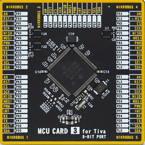
Type
8th Generation
Architecture
ARM Cortex-M4
MCU Memory (KB)
1024
Silicon Vendor
Texas Instruments
Pin count
128
RAM (Bytes)
262144
Used MCU Pins
mikroBUS™ mapper
Take a closer look
Click board™ Schematic

Step by step
Project assembly

Start by selecting your development board and Click board™. Begin with the UNI-DS v8 as your development board.


Software Support
Library Description
This library contains API for SolidSwitch 2 Click driver.
Key functions:
solidswitch2_write_registerThis function writes a desired data to the selected register by using SPI serial interface.solidswitch2_toggle_in0_pinThis function toggles the IN0 pin logic state.solidswitch2_toggle_in1_pinThis function toggles the IN1 pin logic state.
Open Source
Code example
The complete application code and a ready-to-use project are available through the NECTO Studio Package Manager for direct installation in the NECTO Studio. The application code can also be found on the MIKROE GitHub account.
/*!
 * @file main.c
 * @brief SolidSwitch 2 Click example
 *
 * # Description
 * This example demonstrates the use of SolidSwitch 2 Click board by controlling the output state.
 *
 * The demo application is composed of two sections :
 *
 * ## Application Init
 * Initializes the driver and performs the Click default configuration which maps outputs as follows:
 * OUT2   - IN0,
 * OUT3   - IN1,
 * OUT4-5 - PWM GEN,
 * OUT6-7 - PWM LED.
 *
 * ## Application Task
 * Changes the PWM GEN (max to min) and PWM LED (min to max) duty cycle and toggles the IN0 and IN1
 * pins every 250ms. The duty cycle values and INx toggle messages will be displayed on the USB UART.
 *
 * @author Stefan Filipovic
 *
 */

#include "board.h"
#include "log.h"
#include "solidswitch2.h"

static solidswitch2_t solidswitch2;
static log_t logger;

void application_init ( void )
{
    log_cfg_t log_cfg;  /**< Logger config object. */
    solidswitch2_cfg_t solidswitch2_cfg;  /**< Click config object. */

    /**
     * Logger initialization.
     * Default baud rate: 115200
     * Default log level: LOG_LEVEL_DEBUG
     * @note If USB_UART_RX and USB_UART_TX
     * are defined as HAL_PIN_NC, you will
     * need to define them manually for log to work.
     * See @b LOG_MAP_USB_UART macro definition for detailed explanation.
     */
    LOG_MAP_USB_UART( log_cfg );
    log_init( &logger, &log_cfg );
    log_info( &logger, " Application Init " );

    // Click initialization.
    solidswitch2_cfg_setup( &solidswitch2_cfg );
    SOLIDSWITCH2_MAP_MIKROBUS( solidswitch2_cfg, MIKROBUS_1 );
    if ( SPI_MASTER_ERROR == solidswitch2_init( &solidswitch2, &solidswitch2_cfg ) )
    {
        log_error( &logger, " Communication init." );
        for ( ; ; );
    }

    if ( SOLIDSWITCH2_ERROR == solidswitch2_default_cfg ( &solidswitch2 ) )
    {
        log_error( &logger, " Default configuration." );
        for ( ; ; );
    }

    log_info( &logger, " Application Task " );
}

void application_task ( void )
{
    for ( uint16_t duty_cycle = SOLIDSWITCH2_MIN_DUTY_CYCLE; duty_cycle <= SOLIDSWITCH2_MAX_DUTY_CYCLE; duty_cycle += 5 )
    {
        if ( SOLIDSWITCH2_OK == solidswitch2_write_register ( &solidswitch2, SOLIDSWITCH2_REG_PWM_GEN_DC,
                                                              ( uint8_t ) ( SOLIDSWITCH2_MAX_DUTY_CYCLE - duty_cycle ) ) )
        {
            log_printf ( &logger, " PWM GEN DC: %u\r\n", ( SOLIDSWITCH2_MAX_DUTY_CYCLE - duty_cycle ) );
        }
        if ( SOLIDSWITCH2_OK == solidswitch2_write_register ( &solidswitch2, SOLIDSWITCH2_REG_PWM_LED_DC, ( uint8_t ) duty_cycle ) )
        {
            log_printf ( &logger, " PWM LED DC: %u\r\n", duty_cycle );
        }
        solidswitch2_toggle_in0_pin ( &solidswitch2 );
        log_printf ( &logger, " Toggle IN0 pin\r\n" );
        solidswitch2_toggle_in1_pin ( &solidswitch2 );
        log_printf ( &logger, " Toggle IN1 pin\r\n\n" );
        Delay_ms ( 250 );
    }
}

int main ( void )
{
    /* Do not remove this line or clock might not be set correctly. */
    #ifdef PREINIT_SUPPORTED
    preinit();
    #endif

    application_init( );

    for ( ; ; )
    {
        application_task( );
    }

    return 0;
}

// ------------------------------------------------------------------------ END


