Measure temperature and humidity easily with SHT41A and STM32F405RG
Feel comfortable at all times
Published Mar 11, 2023
Click board™
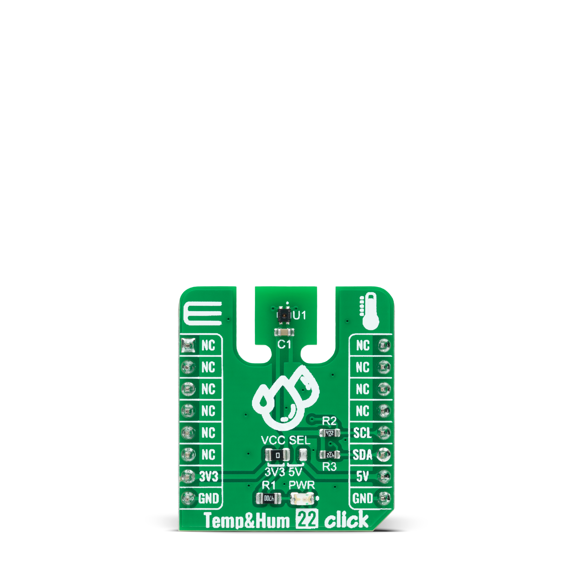
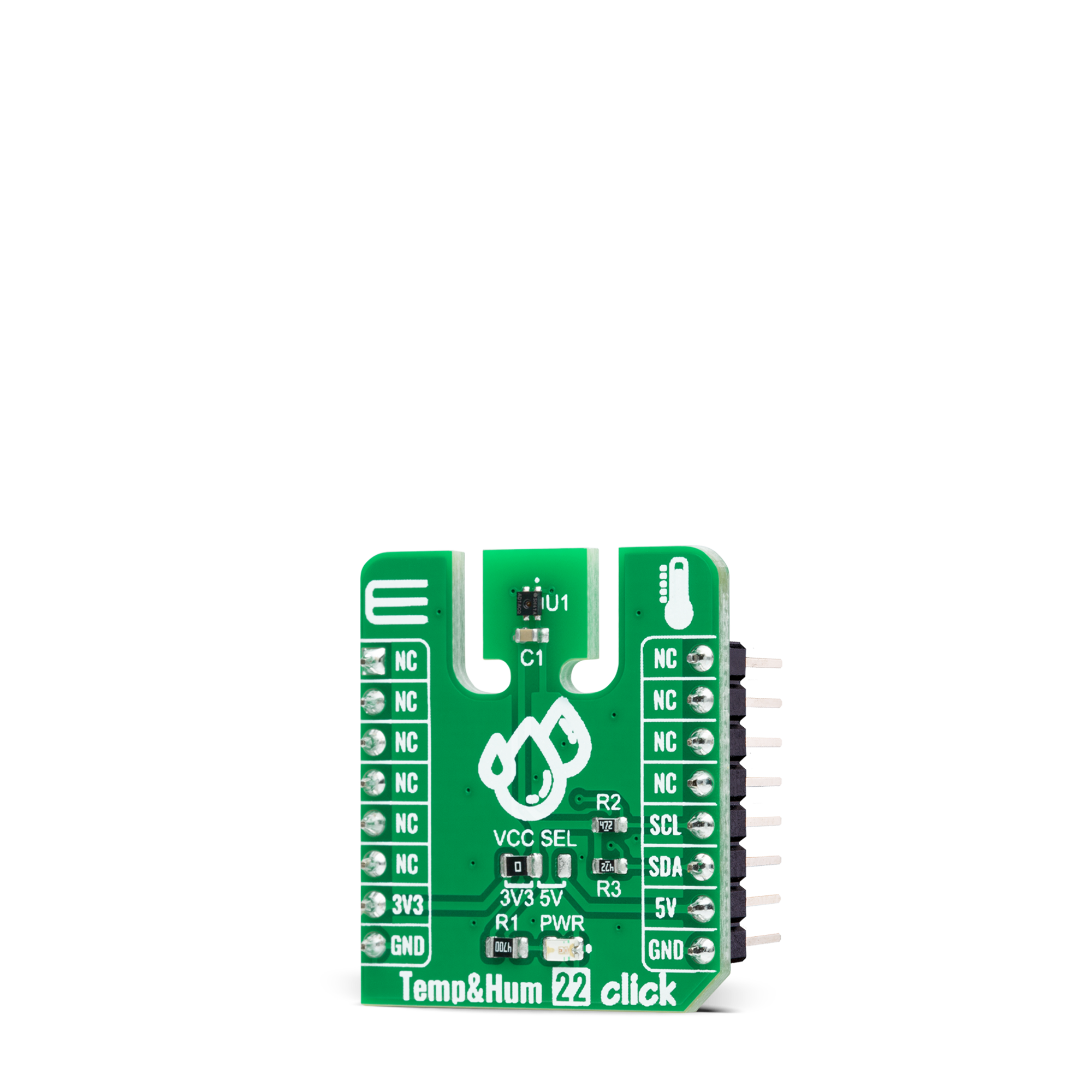
Temp&Hum 22 Click
Dev. board
Fusion for ARM v8
Compiler
NECTO Studio
MCU
STM32F405RG
Reliable temperature and humidity data, even in the most challenging conditions
A
A
Hardware Overview
How does it work?
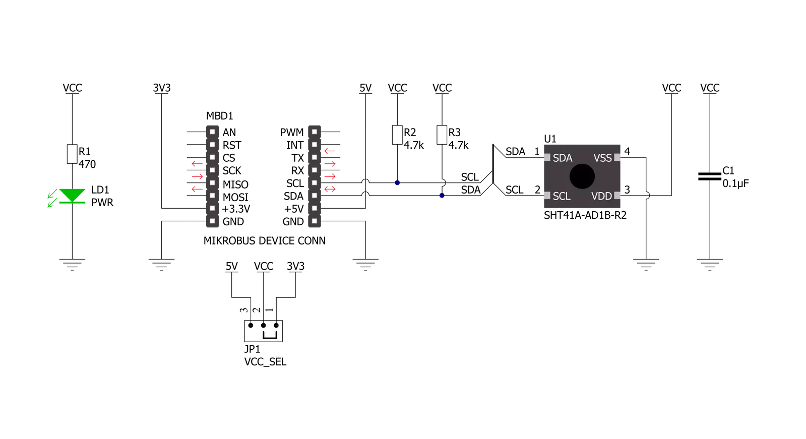
Temp&Hum 22 Click is based on the SHT41A, high-accuracy automotive-grade 16-bit relative humidity and temperature sensor from Sensirion. The SHT41A builds on a wholly new and optimized CMOS chip, offering reduced power consumption, accuracy, and a digital I2C interface for the fastest data transfer. It covers extended operating humidity, and temperature ranges from 0 to 100%RH and from -40°C to 125°C with accuracies of ±1%RH and ±0.3°C. The SHT41A's integrated heater allows advanced on-board-diagnostics alongside reliable operation in harsh conditions such as condensing environments.
The sensor performs best when operated within the recommended average temperature and humidity range of 5-60°C and 20-80%RH. Long-term exposure to conditions outside recommended normal range, especially at high relative humidity, may temporarily offset the RH signal. After returning to the recommended average temperature and humidity range, the sensor will recover to within specifications. Also, to maximize the over-temperature when using the heater, reduced heat conduction and heat capacity of the mounted sensor is desired. For this reason, the sensor is placed on this Click board™ in a particular
position, a piece of a standard PCB with a cutout around the sensor area, increasing the decontamination yield and avoiding excess energy consumption. A PCB layout like this is optimized for minimal thermal heat sink influence. This Click board™ can only be operated with a 3.3V logic voltage level. The board must perform appropriate logic voltage level conversion before using MCUs with different logic levels. However, the Click board™ comes equipped with a library containing functions and an example code that can be used as a reference for further development.
Features overview
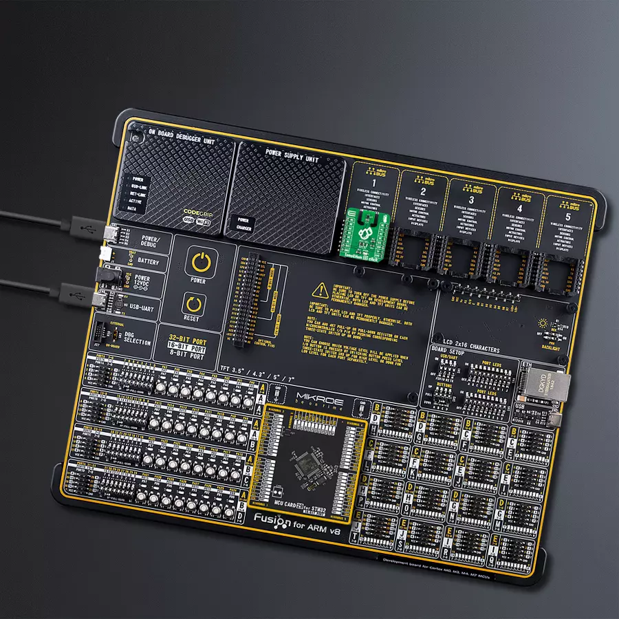
Development board
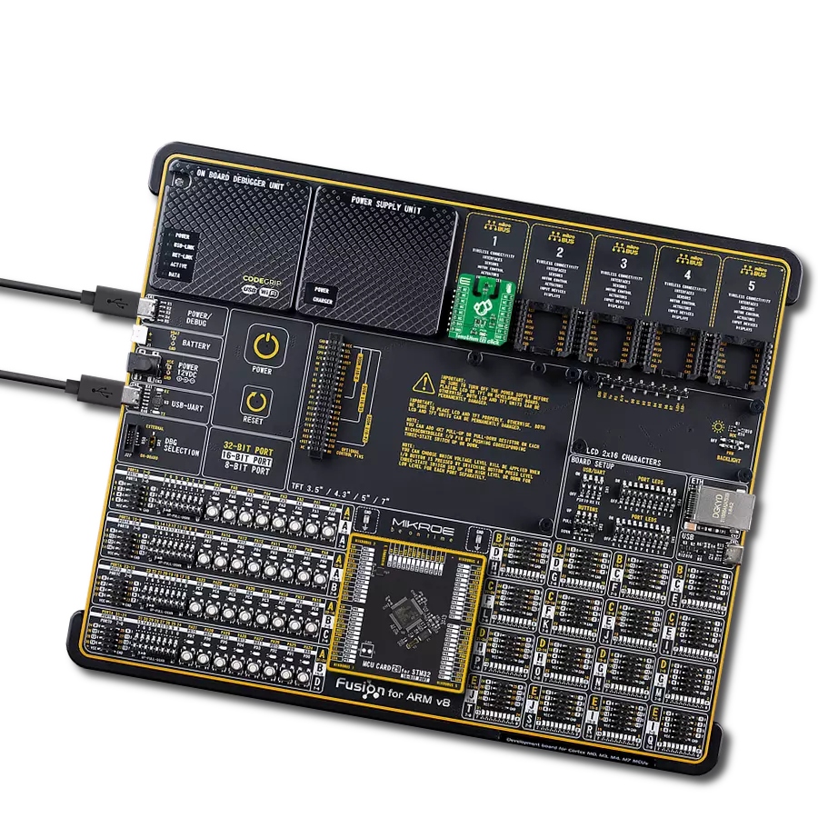
Fusion for ARM v8 is a development board specially designed for the needs of rapid development of embedded applications. It supports a wide range of microcontrollers, such as different ARM® Cortex®-M based MCUs regardless of their number of pins, and a broad set of unique functions, such as the first-ever embedded debugger/programmer over WiFi. The development board is well organized and designed so that the end-user has all the necessary elements, such as switches, buttons, indicators, connectors, and others, in one place. Thanks to innovative manufacturing technology, Fusion for ARM v8 provides a fluid and immersive working experience, allowing access anywhere and under any
circumstances at any time. Each part of the Fusion for ARM v8 development board contains the components necessary for the most efficient operation of the same board. An advanced integrated CODEGRIP programmer/debugger module offers many valuable programming/debugging options, including support for JTAG, SWD, and SWO Trace (Single Wire Output)), and seamless integration with the Mikroe software environment. Besides, it also includes a clean and regulated power supply module for the development board. It can use a wide range of external power sources, including a battery, an external 12V power supply, and a power source via the USB Type-C (USB-C) connector.
Communication options such as USB-UART, USB HOST/DEVICE, CAN (on the MCU card, if supported), and Ethernet is also included. In addition, it also has the well-established mikroBUS™ standard, a standardized socket for the MCU card (SiBRAIN standard), and two display options for the TFT board line of products and character-based LCD. Fusion for ARM v8 is an integral part of the Mikroe ecosystem for rapid development. Natively supported by Mikroe software tools, it covers many aspects of prototyping and development thanks to a considerable number of different Click boards™ (over a thousand boards), the number of which is growing every day.

Microcontroller Overview
MCU Card / MCU
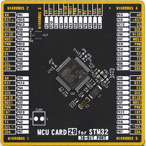
Type
8th Generation
Architecture
ARM Cortex-M4
MCU Memory (KB)
1024
Silicon Vendor
STMicroelectronics
Pin count
64
RAM (Bytes)
196608
Used MCU Pins
mikroBUS™ mapper
Take a closer look
Click board™ Schematic
Step by step
Project assembly

Start by selecting your development board and Click board™. Begin with the Fusion for ARM v8 as your development board.


Track your results in real time
Application Output
1. Application Output - In Debug mode, the 'Application Output' window enables real-time data monitoring, offering direct insight into execution results. Ensure proper data display by configuring the environment correctly using the provided tutorial.

2. UART Terminal - Use the UART Terminal to monitor data transmission via a USB to UART converter, allowing direct communication between the Click board™ and your development system. Configure the baud rate and other serial settings according to your project's requirements to ensure proper functionality. For step-by-step setup instructions, refer to the provided tutorial.

3. Plot Output - The Plot feature offers a powerful way to visualize real-time sensor data, enabling trend analysis, debugging, and comparison of multiple data points. To set it up correctly, follow the provided tutorial, which includes a step-by-step example of using the Plot feature to display Click board™ readings. To use the Plot feature in your code, use the function: plot(*insert_graph_name*, variable_name);. This is a general format, and it is up to the user to replace 'insert_graph_name' with the actual graph name and 'variable_name' with the parameter to be displayed.

Software Support
Library Description
This library contains API for Temp&Hum 22 Click driver.
Key functions:
temphum22_soft_resetThis function performs the software reset by sending the soft reset command.temphum22_read_serial_numThis function reads the 4-bytes unique serial number by using I2C serial interface.temphum22_read_measurement_high_precisionThis function reads the temperature and humidity measurements with high precision.
Open Source
Code example
The complete application code and a ready-to-use project are available through the NECTO Studio Package Manager for direct installation in the NECTO Studio. The application code can also be found on the MIKROE GitHub account.
/*!
 * @file main.c
 * @brief TempHum 22 Click example
 *
 * # Description
 * This example demonstrates the use of Temp & Hum 22 Click board by reading
 * the temperature and humidity data.
 *
 * The demo application is composed of two sections :
 *
 * ## Application Init
 * Initializes the driver, performs the sensor software reset and then reads
 * and displays the sensor unique serial number.
 *
 * ## Application Task
 * Reads the temperature (degC) and the relative humidity (%RH) data and
 * displays the results on the USB UART approximately once per second.
 *
 * @author Stefan Filipovic
 *
 */

#include "board.h"
#include "log.h"
#include "temphum22.h"

static temphum22_t temphum22;
static log_t logger;

void application_init ( void )
{
    log_cfg_t log_cfg;  /**< Logger config object. */
    temphum22_cfg_t temphum22_cfg;  /**< Click config object. */

    /**
     * Logger initialization.
     * Default baud rate: 115200
     * Default log level: LOG_LEVEL_DEBUG
     * @note If USB_UART_RX and USB_UART_TX
     * are defined as HAL_PIN_NC, you will
     * need to define them manually for log to work.
     * See @b LOG_MAP_USB_UART macro definition for detailed explanation.
     */
    LOG_MAP_USB_UART( log_cfg );
    log_init( &logger, &log_cfg );
    log_info( &logger, " Application Init " );

    // Click initialization.
    temphum22_cfg_setup( &temphum22_cfg );
    TEMPHUM22_MAP_MIKROBUS( temphum22_cfg, MIKROBUS_1 );
    if ( I2C_MASTER_ERROR == temphum22_init( &temphum22, &temphum22_cfg ) )
    {
        log_error( &logger, " Communication init." );
        for ( ; ; );
    }

    if ( TEMPHUM22_OK == temphum22_soft_reset ( &temphum22 ) )
    {
        log_printf ( &logger, " Software reset\r\n" );
    }
    Delay_1sec ( );

    uint32_t serial_num;
    if ( TEMPHUM22_OK == temphum22_read_serial_num ( &temphum22, &serial_num ) )
    {
        log_printf ( &logger, " Serial number: 0x%.8LX\r\n", serial_num );
    }

    log_info( &logger, " Application Task " );
}

void application_task ( void )
{
    float temperature, humidity;
    if ( TEMPHUM22_OK == temphum22_read_measurement_high_precision ( &temphum22, &temperature, &humidity ) )
    {
        log_printf ( &logger, " Temperature: %.2f degC\r\n", temperature );
        log_printf ( &logger, " Humidity: %.2f %%RH\r\n\n", humidity );
        Delay_ms ( 1000 );
    }
}

int main ( void )
{
    /* Do not remove this line or clock might not be set correctly. */
    #ifdef PREINIT_SUPPORTED
    preinit();
    #endif

    application_init( );

    for ( ; ; )
    {
        application_task( );
    }

    return 0;
}

// ------------------------------------------------------------------------ END
Additional Support
Resources
Category:Temperature & humidity


