使用MAX7219和MK64FN1M0VDC12最大化您的视觉效果,使用双绿色5x7显示器
双倍显示,双倍冲击:绿色5x7的魔力!
已发布 6月 26, 2024
点击板
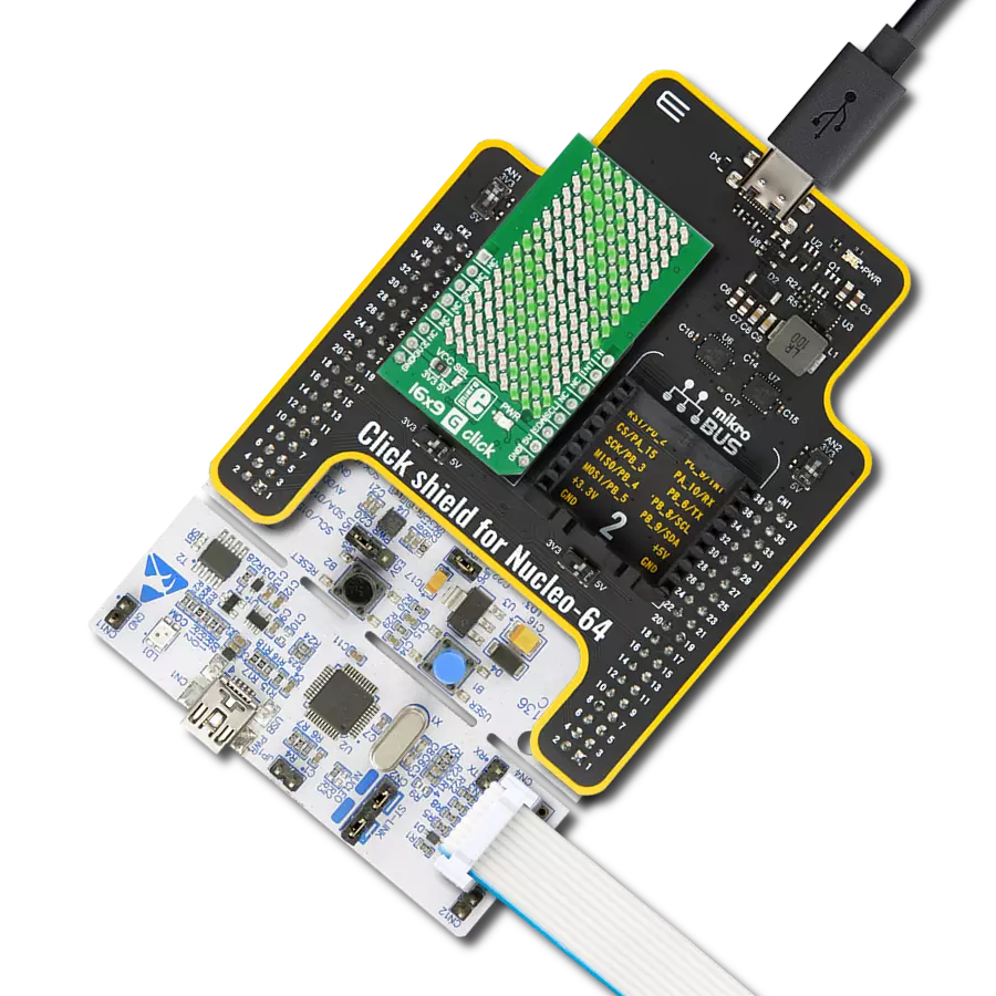
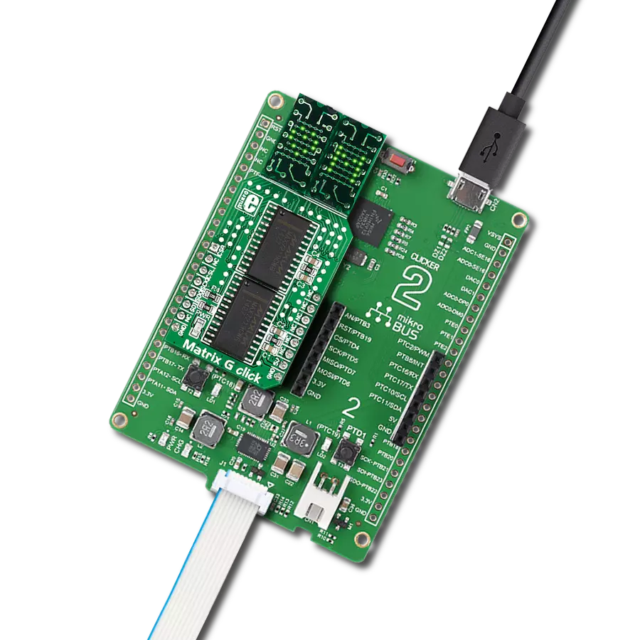
Matrix G Click
开发板
Clicker 2 for Kinetis
编译器
NECTO Studio
微控制器单元
MK64FN1M0VDC12
以效率和多功能为重点,我们致力于为开发者提供双绿色矩阵解决方案,实现对两个显示器的同步控制,从而产生动态而引人注目的视觉效果。
A
A
硬件概览
它是如何工作的?
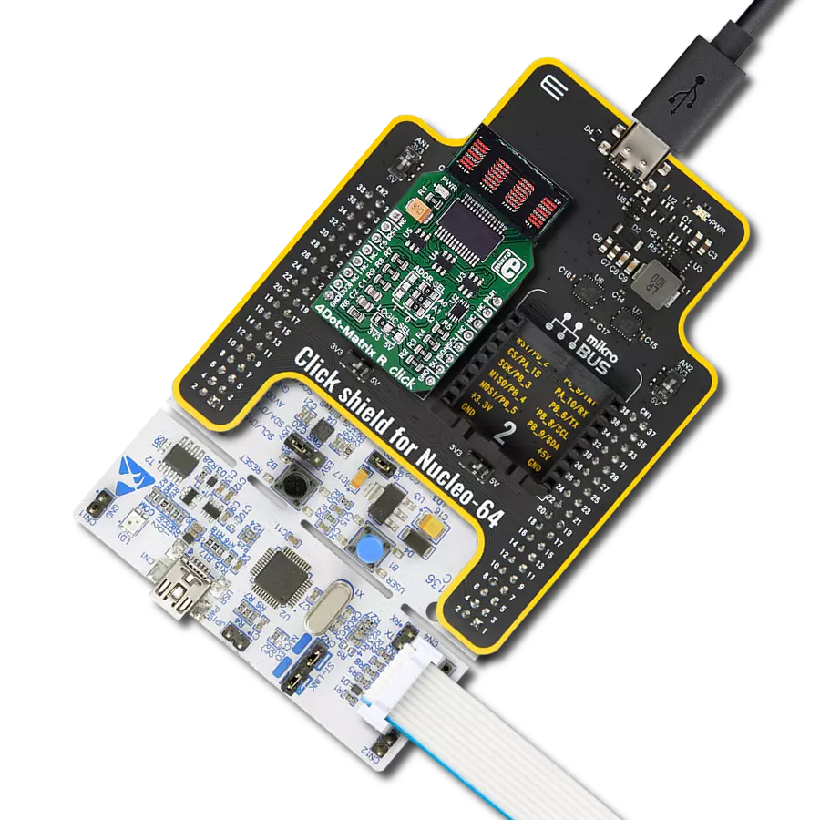
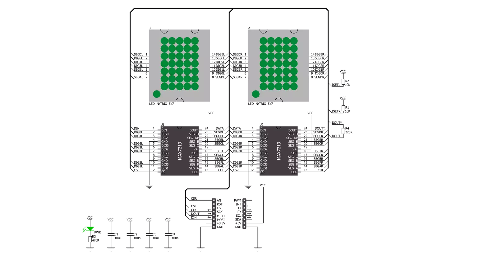
Matrix G Click基于来自Analog Devices的两个MAX7219,通过串行接口连接的8位LED显示驱动器。MAX7219在10MHz的串行接口上可以单独或同时寻址两个板载绿色5x7矩阵的每个LED。它具有数字和模拟亮度控制、上电时显示关闭、低功耗关断并保留数据等功能。它还包括BCD码-B解码器、多路复用扫描电路、段和数字驱动器以及一个存储每个数据的8x8静态RAM。如果用户在具有两个相邻
mikroBUS™插座的板上使用两个 Click板,例如Fusion、Clicker 2或Flip&Click,则可以获得四个字符的显示。Matrix G Click使用SPI串行接口与主机微控制器通信,速度高达10MHz。每个MAX7219的片选引脚连接到相应的mikroBUS™插座上的引脚。控制左侧显示 的MAX7219连接到标记为CSL的引脚,而右侧连接到标记为CSR的引脚。串行数据在相应的片选引脚处处于低逻辑状态时加载到移位
寄存器中。峰值段电流通过外部电阻设置为约40mA。显示的亮度可以通过软件控制内部PWM来调节。该Click板™只能使用5V逻辑电压级别操作。在使用具有不同逻辑电平的MCU之前,板子必须执行适当的逻辑电压级别转换。此外,它配备了一个包含函数和示例代码的库,可用作进一步开发的参考。


功能概述
开发板
Clicker 2 for Kinetis 是一款紧凑型入门开发板,它将 Click 板™的灵活性带给您喜爱的微控制器,使其成为实现您想法的完美入门套件。它配备了一款板载 32 位 ARM Cortex-M4F 微控制器,NXP 半导体公司的 MK64FN1M0VDC12,两个 mikroBUS™ 插槽用于 Click 板™连接,一个 USB 连接器,LED 指示灯,按钮,一个 JTAG 程序员连接器以及两个 26 针头用于与外部电子设备的接口。其紧凑的设计和清晰、易识别的丝网标记让您能够迅速构建具有独特功能和特性
的小工具。Clicker 2 for Kinetis 开发套件的每个部分 都包含了使同一板块运行最高效的必要组件。除了可以选择 Clicker 2 for Kinetis 的编程方式,使用 USB HID mikroBootloader 或外部 mikroProg 连接器进行 Kinetis 编程外,Clicker 2 板还包括一个干净且调节过的开发套件电源供应模块。它提供了两种供电方式;通过 USB Micro-B 电缆,其中板载电压调节器为板上每个组件提供适当的电压水平,或使用锂聚合物 电池通过板载电池连接器供电。所有 mikroBUS™ 本
身支持的通信方法都在这块板上,包括已经建立良好的 mikroBUS™ 插槽、重置按钮和几个用户可配置的按钮及 LED 指示灯。Clicker 2 for Kinetis 是 Mikroe 生态系统的一个组成部分,允许您在几分钟内创建新的应用程序。它由 Mikroe 软件工具原生支持,得益于大量不同的 Click 板™(超过一千块板),其数量每天都在增长,它涵盖了原型制作的许多方面。

微控制器概述
MCU卡片 / MCU

建筑
ARM Cortex-M4
MCU 内存 (KB)
1024
硅供应商
NXP
引脚数
121
RAM (字节)
262144
使用的MCU引脚
mikroBUS™映射器
“仔细看看!”
Click board™ 原理图
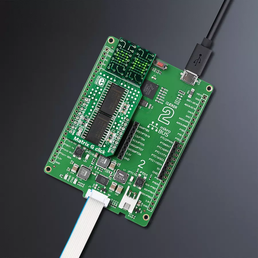
一步一步来
项目组装

从选择您的开发板和Click板™开始。以Clicker 2 for Kinetis作为您的开发板开始。


软件支持
库描述
这个库包含了 Matrix G Click 驱动程序的 API。
关键函数:
matrixg_display_characters- 在点击的 L/R 段上显示指定的字符matrixg_set_csn_high- 将 CSN 引脚输出设置为高matrixg_set_csn_low- 将 CSN 引脚输出设置为低
开源
代码示例
完整的应用程序代码和一个现成的项目可以通过NECTO Studio包管理器直接安装到NECTO Studio。 应用程序代码也可以在MIKROE的GitHub账户中找到。
/*!
 * @file main.c
 * @brief MatrixG Click example
 *
 * # Description
 * This example showcases how to prepare the logger and Click modules for use and
 * how to display ASCII characters on both of the LED segments of the Click.
 *
 * The demo application is composed of two sections :
 *
 * ## Application Init
 * This function initializes and configures the logger and Click modules. After the initialization of the logger module,
 * communication, mikrobus and pin setup, some of the registers are configured in order for the Click module to work properly.
 *
 * ## Application Task
 * This function displays two strings on each of the LED segments, showing one character every second.
 * It should display " Mikroelektronika" on the left one and "Mikroelektronika " on the right.
 *
 * @note
 * The Click has two chips, each controlling one of the LED segments, on and requires you to write data to both at the same time.
 * Writing to one specific chip will not work. If you wish to display characters on a single segment, you have to send ' ' characters to the other segment.
 *
 * @author Jelena Milosavljevic
 *
 */

// ------------------------------------------------------------------- INCLUDES

#include "board.h"
#include "log.h"
#include "matrixg.h"

// ------------------------------------------------------------------ VARIABLES

static matrixg_t matrixg;
static log_t logger;

// ------------------------------------------------------ APPLICATION FUNCTIONS

void application_init ( ) {

    log_cfg_t log_cfg;
    matrixg_cfg_t cfg;

    /**
     * Logger initialization.
     * Default baud rate: 115200
     * Default log level: LOG_LEVEL_DEBUG
     * @note If USB_UART_RX and USB_UART_TX
     * are defined as HAL_PIN_NC, you will
     * need to define them manually for log to work.
     * See @b LOG_MAP_USB_UART macro definition for detailed explanation.
     */
    LOG_MAP_USB_UART( log_cfg );
    log_init( &logger, &log_cfg );
    log_info( &logger, "---- Application Init ----" );

    //  Click initialization.

    matrixg_cfg_setup( &cfg );
    MATRIXG_MAP_MIKROBUS( cfg, MIKROBUS_1 );
    matrixg_init( &matrixg, &cfg );
    Delay_ms ( 100 );
    matrixg_default_cfg( &matrixg );
    Delay_ms ( 100 );
}

void application_task ( ) {

    matrixg_display_characters( &matrixg, ' ', 'M' );
    Delay_ms ( 1000 );
    matrixg_display_characters( &matrixg, 'M', 'i' );
    Delay_ms ( 1000 );
    matrixg_display_characters( &matrixg, 'i', 'k' );
    Delay_ms ( 1000 );
    matrixg_display_characters( &matrixg, 'k', 'r' );
    Delay_ms ( 1000);
    matrixg_display_characters( &matrixg, 'r', 'o' );
    Delay_ms ( 1000 );
    matrixg_display_characters( &matrixg, 'o', 'E' );
    Delay_ms ( 1000 );
    matrixg_display_characters( &matrixg, 'E', 'l' );
    Delay_ms ( 1000 );
    matrixg_display_characters( &matrixg, 'l', 'e' );
    Delay_ms ( 1000 );
    matrixg_display_characters( &matrixg, 'e', 'k' );
    Delay_ms ( 1000 );
    matrixg_display_characters( &matrixg, 'k', 't' );
    Delay_ms ( 1000 );
    matrixg_display_characters( &matrixg, 't', 'r' );
    Delay_ms ( 1000 );
    matrixg_display_characters( &matrixg, 'r', 'o' );
    Delay_ms ( 1000 );
    matrixg_display_characters( &matrixg, 'o', 'n' );
    Delay_ms ( 1000 );
    matrixg_display_characters( &matrixg, 'n', 'i' );
    Delay_ms ( 1000 );
    matrixg_display_characters( &matrixg, 'i', 'k' );
    Delay_ms ( 1000 );
    matrixg_display_characters( &matrixg, 'k', 'a' );
    Delay_ms ( 100 );
    matrixg_display_characters( &matrixg, 'a', ' ' );
    Delay_ms ( 100 );
}

int main ( void )
{
    /* Do not remove this line or clock might not be set correctly. */
    #ifdef PREINIT_SUPPORTED
    preinit();
    #endif

    application_init( );

    for ( ; ; )
    {
        application_task( );
    }

    return 0;
}

// ------------------------------------------------------------------------ END