Measure the intensity of ambient light with APM-16D24-310-DF8/TR8 and PIC32MZ1024EFH064
Better light, better sight
Published Mar 12, 2023
Click board™
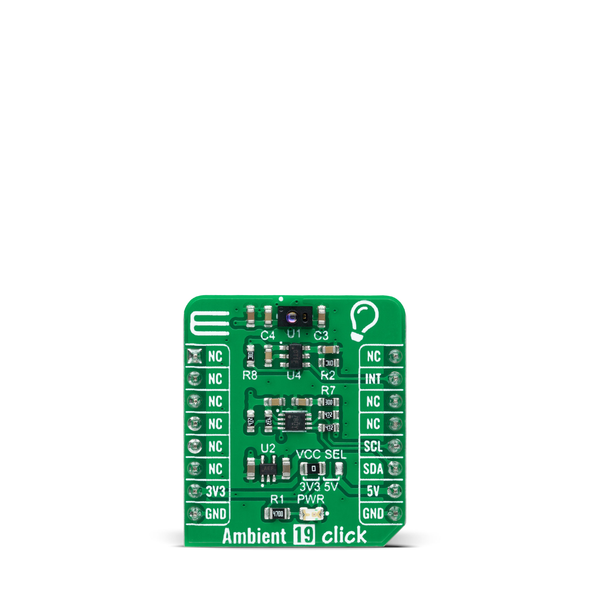
Ambient 19 Click
Dev. board
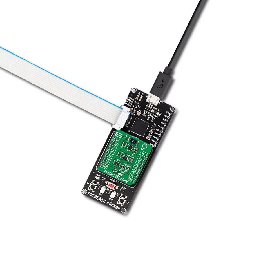
PIC32MZ clicker
Compiler
NECTO Studio
MCU
PIC32MZ1024EFH064
Convert ambient light into the most accurate Lux values
A
A
Hardware Overview
How does it work?
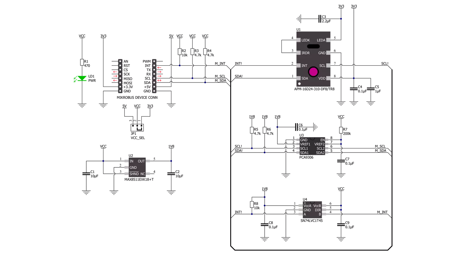
Ambient 19 Click is based on the APM-16D24-310-DF8/TR8, a digital I2C interface sensor that integrates Ambient Light Sensor (ALS), Proximity Sensor (PS), and Infrared LED (IR LED) from Everlight Electronics. The ALS can sense ambient light intensity that matches the human eye's response and enable the device to implement display dimming or lighting brightness control functions, helping to reduce power consumption. Also, the proximity sensor uses an IR LED reflection function to detect "away or close" to the object, triggering the device to turn ON/OFF or some other specific function. Three photodiodes are built in the APM-16D24-310-DF8/TR8, where each photodiode responds to different light spectra. This feature can distinguish different light sources and derive different illuminance conversion formulas according to various light sources.
Also, it has a flexible and wide operating range for the ambient light sensor with a maximum resolution of 0.0023lux/count and full detectable illumination of 57880Lux. An integrated proximity function has an adjustable number of IR pulses from 1 to 256 alongside a flexible IR LED driving current to meet different application requirements. An integrated filter also reduces unwanted IR signals and environmental noise. The APM-16D24-310-DF8/TR8 does not require a specific Power-Up sequence but requires a voltage of 1.8V for its interface and logic part to work correctly. Therefore, a small regulating LDO, the MAX8511, is used, providing a 1.8V out of either 5V or 3.3V mikroBUS™ power rails. Ambient 19 Click communicates with MCU using the standard I2C 2-Wire interface with a maximum clock frequency of 400kHz, fully adjustable through software registers.
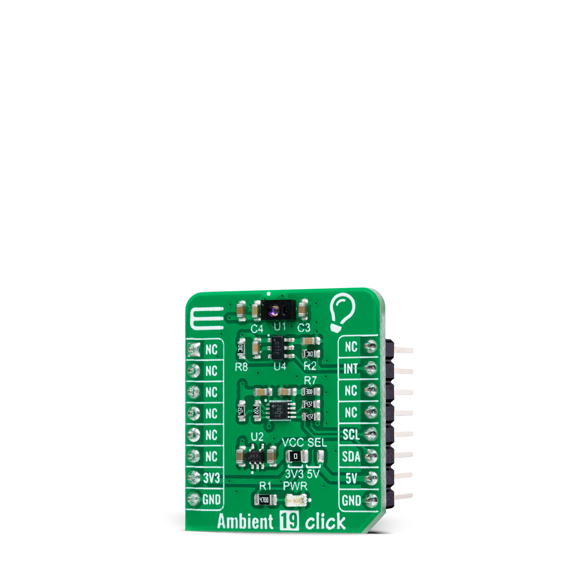
Since the sensor for operation requires a power supply of 3.3V, this Click board™ also features the PCA9306 and SN74LVC1T45 voltage-level translators. The I2C interface bus lines are routed to the voltage-level translators allowing this Click board™ to work with both 3.3V and 5V MCUs properly. It also possesses an additional interrupt signal, routed on the INT pin of the mikroBUS™ socket, indicating when a specific interrupt event occurs, such as detecting a meaningful change in light intensity. This Click board™ can operate with either 3.3V or 5V logic voltage levels selected via the VCC SEL jumper. This way, both 3.3V and 5V capable MCUs can use the communication lines properly. However, the Click board™ comes equipped with a library containing easy-to-use functions and an example code that can be used, as a reference, for further development.
Features overview
Development board
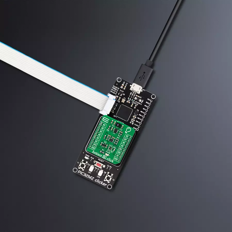
PIC32MZ Clicker is a compact starter development board that brings the flexibility of add-on Click boards™ to your favorite microcontroller, making it a perfect starter kit for implementing your ideas. It comes with an onboard 32-bit PIC32MZ microcontroller with FPU from Microchip, a USB connector, LED indicators, buttons, a mikroProg connector, and a header for interfacing with external electronics. Thanks to its compact design with clear and easy-recognizable silkscreen markings, it provides a fluid and immersive working experience, allowing access anywhere and under
any circumstances. Each part of the PIC32MZ Clicker development kit contains the components necessary for the most efficient operation of the same board. In addition to the possibility of choosing the PIC32MZ Clicker programming method, using USB HID mikroBootloader, or through an external mikroProg connector for PIC, dsPIC, or PIC32 programmer, the Clicker board also includes a clean and regulated power supply module for the development kit. The USB Micro-B connection can provide up to 500mA of current, which is more than enough to operate all onboard
and additional modules. All communication methods that mikroBUS™ itself supports are on this board, including the well-established mikroBUS™ socket, reset button, and several buttons and LED indicators. PIC32MZ Clicker is an integral part of the Mikroe ecosystem, allowing you to create a new application in minutes. Natively supported by Mikroe software tools, it covers many aspects of prototyping thanks to a considerable number of different Click boards™ (over a thousand boards), the number of which is growing every day.

Microcontroller Overview
MCU Card / MCU

Architecture
PIC32
MCU Memory (KB)
1024
Silicon Vendor
Microchip
Pin count
64
RAM (Bytes)
524288
Used MCU Pins
mikroBUS™ mapper
Take a closer look
Click board™ Schematic
Step by step
Project assembly

Start by selecting your development board and Click board™. Begin with the PIC32MZ clicker as your development board.


Software Support
Library Description
This library contains API for Ambient 19 Click driver.
Key functions:
ambient19_measure_light_levelThis function reads the raw ALS data from two channels and then measures the light level in lux based on those readings.ambient19_read_raw_proximityThis function reads the raw PS and IR data of the proximity sensor.ambient19_clear_interruptsThis function clears all interrupts by clearing the INT_FLAG register.
Open Source
Code example
The complete application code and a ready-to-use project are available through the NECTO Studio Package Manager for direct installation in the NECTO Studio. The application code can also be found on the MIKROE GitHub account.
/*!
 * @file main.c
 * @brief Ambient19 Click example
 *
 * # Description
 * This example demonstrates the use of Ambient 19 Click board by measuring
 * the ambient light level in Lux.
 *
 * The demo application is composed of two sections :
 *
 * ## Application Init
 * Initializes the driver and performs the Click default configuration.
 *
 * ## Application Task
 * Waits for the data ready interrupt, then reads the ambient light level in Lux as well as
 * the raw proximity data of PS and IR leds and displays the results on the USB UART.
 * By default, the data ready interrupt triggers upon every ADC cycle which will be
 * performed every 500ms approximately.
 *
 * @author Stefan Filipovic
 *
 */

#include "board.h"
#include "log.h"
#include "ambient19.h"

static ambient19_t ambient19;
static log_t logger;

void application_init ( void )
{
    log_cfg_t log_cfg;  /**< Logger config object. */
    ambient19_cfg_t ambient19_cfg;  /**< Click config object. */

    /**
     * Logger initialization.
     * Default baud rate: 115200
     * Default log level: LOG_LEVEL_DEBUG
     * @note If USB_UART_RX and USB_UART_TX
     * are defined as HAL_PIN_NC, you will
     * need to define them manually for log to work.
     * See @b LOG_MAP_USB_UART macro definition for detailed explanation.
     */
    LOG_MAP_USB_UART( log_cfg );
    log_init( &logger, &log_cfg );
    log_info( &logger, " Application Init " );

    // Click initialization.
    ambient19_cfg_setup( &ambient19_cfg );
    AMBIENT19_MAP_MIKROBUS( ambient19_cfg, MIKROBUS_1 );
    if ( I2C_MASTER_ERROR == ambient19_init( &ambient19, &ambient19_cfg ) )
    {
        log_error( &logger, " Communication init." );
        for ( ; ; );
    }

    if ( AMBIENT19_ERROR == ambient19_default_cfg ( &ambient19 ) )
    {
        log_error( &logger, " Default configuration." );
        for ( ; ; );
    }

    log_info( &logger, " Application Task " );
}

void application_task ( void )
{
    if ( !ambient19_get_int_pin ( &ambient19 ) )
    {
        uint16_t lux, ps_data, ir_data;
        if ( AMBIENT19_OK == ambient19_measure_light_level ( &ambient19, &lux ) )
        {
            log_printf ( &logger, "\r\n Ambient light level [Lux]: %u\r\n", lux );
        }
        if ( AMBIENT19_OK == ambient19_read_raw_proximity ( &ambient19, &ps_data, &ir_data ) )
        {
            log_printf ( &logger, " PS data: %u\r\n", ps_data );
            log_printf ( &logger, " IR data: %u\r\n", ir_data );
        }
        ambient19_clear_interrupts ( &ambient19 );
    }
}

int main ( void )
{
    /* Do not remove this line or clock might not be set correctly. */
    #ifdef PREINIT_SUPPORTED
    preinit();
    #endif

    application_init( );

    for ( ; ; )
    {
        application_task( );
    }

    return 0;
}

// ------------------------------------------------------------------------ END
Additional Support
Resources
Category:Optical


