Design a portable color analyzer with CLS-16D24-44-DF8/TR8 and STM32F031K6
Sensing the rainbow!

Published Oct 01, 2024
Click board™
Color 15 Click
Dev. board
Nucleo 32 with STM32F031K6 MCU
Compiler
NECTO Studio
MCU
STM32F031K6
Get the colors you need with our highly sensitive and accurate color-sensing solution
A
A
Hardware Overview
How does it work?
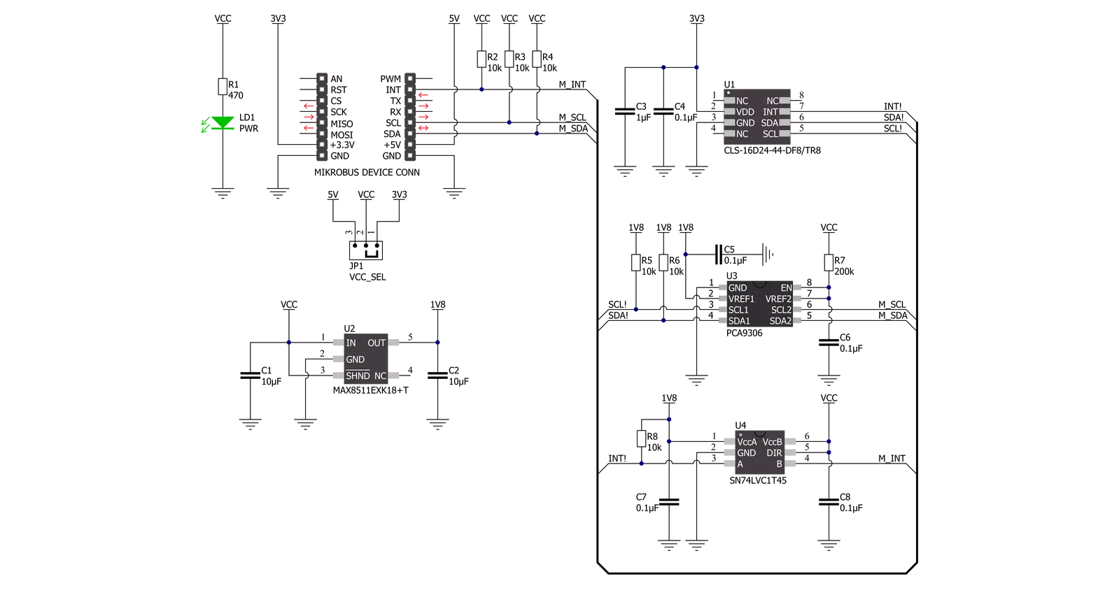
Color 15 Click is based on the CLS-16D24-44-DF8/TR8, a digital I2C compatible interface color light sensor from Everlight Electronics. It supports parallel output for Red, Green, Blue, White, and Infrared light (R, G, B, W, IR) and converts them to a 16-bit digital value (0-65535). This sensor is characterized by high resolution designed to reject IR in light sources allowing the device to operate in environments from sunlight to dark rooms, with a maximum detection lux of 204.679lux. Besides, an integrated ADC rejects 50Hz and 60Hz flickers caused by artificial light sources. It also has stable performance over a wide temperature range of -40°C to 65°C, suitable for measuring the present color light.
The CLS-16D24-44-DF8/TR8 does not require a specific Power-Up sequence but requires a voltage of 1.8V for its interface and logic part to work correctly. Therefore, a small regulating LDO, the MAX8511, provides a 1.8V out of selected mikroBUS™ power rail. Color 15 Click communicates with MCU using the standard I2C 2-Wire interface with a maximum clock frequency of 400kHz, fully adjustable through software registers. Since the sensor for operation requires a power supply of 3.3V, this Click board™ also features the PCA9306 and SN74LVC1T45 voltage-level translators. The I2C interface bus lines are routed to the voltage-level translators allowing this Click board™ to work with both 3.3V and 5V MCUs properly.
Also, it uses an interrupt pin, the INT pin of the mikroBUS™ socket, used when an interrupt occurs to alert the system when the color result crosses upper or lower threshold settings. This Click board™ can operate with either 3.3V or 5V logic voltage levels selected via the VCC SEL jumper. This way, both 3.3V and 5V capable MCUs can use the communication lines properly. However, the Click board™ comes equipped with a library containing easy-to-use functions and an example code that can be used, as a reference, for further development.


Features overview
Development board
Nucleo 32 with STM32F031K6 MCU board provides an affordable and flexible platform for experimenting with STM32 microcontrollers in 32-pin packages. Featuring Arduino™ Nano connectivity, it allows easy expansion with specialized shields, while being mbed-enabled for seamless integration with online resources. The
board includes an on-board ST-LINK/V2-1 debugger/programmer, supporting USB reenumeration with three interfaces: Virtual Com port, mass storage, and debug port. It offers a flexible power supply through either USB VBUS or an external source. Additionally, it includes three LEDs (LD1 for USB communication, LD2 for power,
and LD3 as a user LED) and a reset push button. The STM32 Nucleo-32 board is supported by various Integrated Development Environments (IDEs) such as IAR™, Keil®, and GCC-based IDEs like AC6 SW4STM32, making it a versatile tool for developers.

Microcontroller Overview
MCU Card / MCU

Architecture
ARM Cortex-M0
MCU Memory (KB)
32
Silicon Vendor
STMicroelectronics
Pin count
32
RAM (Bytes)
4096
You complete me!
Accessories
Click Shield for Nucleo-32 is the perfect way to expand your development board's functionalities with STM32 Nucleo-32 pinout. The Click Shield for Nucleo-32 provides two mikroBUS™ sockets to add any functionality from our ever-growing range of Click boards™. We are fully stocked with everything, from sensors and WiFi transceivers to motor control and audio amplifiers. The Click Shield for Nucleo-32 is compatible with the STM32 Nucleo-32 board, providing an affordable and flexible way for users to try out new ideas and quickly create prototypes with any STM32 microcontrollers, choosing from the various combinations of performance, power consumption, and features. The STM32 Nucleo-32 boards do not require any separate probe as they integrate the ST-LINK/V2-1 debugger/programmer and come with the STM32 comprehensive software HAL library and various packaged software examples. This development platform provides users with an effortless and common way to combine the STM32 Nucleo-32 footprint compatible board with their favorite Click boards™ in their upcoming projects.

Used MCU Pins
mikroBUS™ mapper
Take a closer look
Click board™ Schematic
Step by step
Project assembly

Start by selecting your development board and Click board™. Begin with the Nucleo 32 with STM32F031K6 MCU as your development board.


Track your results in real time
Application Output
1. Application Output - In Debug mode, the 'Application Output' window enables real-time data monitoring, offering direct insight into execution results. Ensure proper data display by configuring the environment correctly using the provided tutorial.

2. UART Terminal - Use the UART Terminal to monitor data transmission via a USB to UART converter, allowing direct communication between the Click board™ and your development system. Configure the baud rate and other serial settings according to your project's requirements to ensure proper functionality. For step-by-step setup instructions, refer to the provided tutorial.

3. Plot Output - The Plot feature offers a powerful way to visualize real-time sensor data, enabling trend analysis, debugging, and comparison of multiple data points. To set it up correctly, follow the provided tutorial, which includes a step-by-step example of using the Plot feature to display Click board™ readings. To use the Plot feature in your code, use the function: plot(*insert_graph_name*, variable_name);. This is a general format, and it is up to the user to replace 'insert_graph_name' with the actual graph name and 'variable_name' with the parameter to be displayed.

Software Support
Library Description
This library contains API for Color 15 Click driver.
Key functions:
color15_get_dataThis function reads data from 5 channels (Red, Green, Blue, White, IR).color15_rgbw_to_hslThis function converts RGBW (red, green, blue, white) to HSL (hue, saturation, lightness) color value.color15_get_colorThis function returns the color name flag from the input HSL color.
Open Source
Code example
The complete application code and a ready-to-use project are available through the NECTO Studio Package Manager for direct installation in the NECTO Studio. The application code can also be found on the MIKROE GitHub account.
/*!
 * @file main.c
 * @brief Color15 Click example
 *
 * # Description
 * This example demonstrates the use of Color 15 Click board by reading data
 * from 5 channels and converting them to HSL color and displaying those data as
 * well as the detected color name on the USB UART.
 *
 * The demo application is composed of two sections :
 *
 * ## Application Init
 * Initializes the driver and performs the Click default configuration.
 *
 * ## Application Task
 * Waits for the data ready interrupt, then reads the values of all channels and converts
 * them to HSL color and displays those data as well as the detected color name on the USB UART
 * every 500ms approximately.
 *
 * @author Stefan Filipovic
 *
 */

#include "board.h"
#include "log.h"
#include "color15.h"

static color15_t color15;
static log_t logger;

void application_init ( void )
{
    log_cfg_t log_cfg;  /**< Logger config object. */
    color15_cfg_t color15_cfg;  /**< Click config object. */

    /**
     * Logger initialization.
     * Default baud rate: 115200
     * Default log level: LOG_LEVEL_DEBUG
     * @note If USB_UART_RX and USB_UART_TX
     * are defined as HAL_PIN_NC, you will
     * need to define them manually for log to work.
     * See @b LOG_MAP_USB_UART macro definition for detailed explanation.
     */
    LOG_MAP_USB_UART( log_cfg );
    log_init( &logger, &log_cfg );
    log_info( &logger, " Application Init " );

    // Click initialization.
    color15_cfg_setup( &color15_cfg );
    COLOR15_MAP_MIKROBUS( color15_cfg, MIKROBUS_1 );
    if ( I2C_MASTER_ERROR == color15_init( &color15, &color15_cfg ) )
    {
        log_error( &logger, " Communication init." );
        for ( ; ; );
    }

    if ( COLOR15_ERROR == color15_default_cfg ( &color15 ) )
    {
        log_error( &logger, " Default configuration." );
        for ( ; ; );
    }

    log_info( &logger, " Application Task " );
}

void application_task ( void )
{
    // Wait for the data ready interrupt indication
    while ( color15_get_int_pin ( &color15 ) );

    color15_channels_t channels;
    if ( ( COLOR15_OK == color15_clear_interrupt ( &color15 ) ) &&
         ( COLOR15_OK == color15_get_data ( &color15, &channels ) ) )
    {
        color15_hsl_t hsl;
        color15_rgbw_to_hsl ( &color15, &channels, &hsl );
        log_printf ( &logger, "\r\n Hue: %.1f deg\r\n", hsl.hue );
        log_printf ( &logger, " Saturation: %.1f %%\r\n", hsl.saturation );
        log_printf ( &logger, " Lightness: %.1f %%\r\n", hsl.lightness );
        switch ( color15_get_color ( &hsl ) )
        {
            case COLOR15_RED_COLOR:
            {
                log_printf( &logger, " Color: RED\r\n" );
                break;
            }
            case COLOR15_YELLOW_COLOR:
            {
                log_printf( &logger, " Color: YELLOW\r\n" );
                break;
            }
            case COLOR15_GREEN_COLOR:
            {
                log_printf( &logger, " Color: GREEN\r\n" );
                break;
            }
            case COLOR15_CYAN_COLOR:
            {
                log_printf( &logger, " Color: CYAN\r\n" );
                break;
            }
            case COLOR15_BLUE_COLOR:
            {
                log_printf( &logger, " Color: BLUE\r\n" );
                break;
            }
            case COLOR15_MAGENTA_COLOR:
            {
                log_printf( &logger, " Color: MAGENTA\r\n" );
                break;
            }
            case COLOR15_WHITE_COLOR:
            {
                log_printf( &logger, " Color: WHITE\r\n" );
                break;
            }
            case COLOR15_BLACK_COLOR:
            {
                log_printf( &logger, " Color: BLACK\r\n" );
                break;
            }
            default:
            {
                log_printf( &logger, " Color: UNKNOWN\r\n" );
                break;
            }
        }
    }
}

int main ( void )
{
    /* Do not remove this line or clock might not be set correctly. */
    #ifdef PREINIT_SUPPORTED
    preinit();
    #endif

    application_init( );

    for ( ; ; )
    {
        application_task( );
    }

    return 0;
}

// ------------------------------------------------------------------------ END


