Have smooth and precise movement control with 2765 and PIC32MZ1024EFH064
Navigate your way to success

Published Mar 09, 2023
Click board™
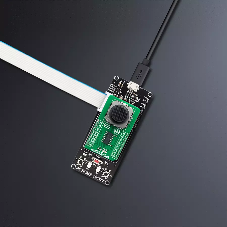
Joystick 3 Click
Dev. board
PIC32MZ clicker
Compiler
NECTO Studio
MCU
PIC32MZ1024EFH064
Perform the full range of motion in all directions
A
A
Hardware Overview
How does it work?
Joystick 3 Click is based on 2765, a high-quality mini 2-axis analog-type thumbstick from Adafruit Industries. This type of joystick has a self-centering feature that allows it to center itself the moment when you release the joystick. It also contains a comfortable cup-type black knob/cap, which gives the feel of a thumbstick, making it very similar to the 'analog' joysticks on PSP joysticks, suitable for numerous applications as a human-machine interface. It comprises two 10kΩ potentiometers, one for up/down and another for left/right direction, used as dual adjustable voltage dividers providing 2-axis analog input in a control stick form. With the joystick fully assembled and functioning, the voltage will
follow the motion of the thumbstick as it is moved around. The measurements of the potentiometer resistance change are needed to read the joystick's physical position. For that reason, the MCP3204, a 12-bit A/D converter from Microchip, connects the joystick with mikroBUS™ using a simple serial interface compatible with the SPI protocol to determine the value of the joystick's X and Y. As the MCP3204 has a resolution of 12 bits, the values on each analog channel (axis) can vary from 0 to 4095. So, if the stick is moved on the X axis from one end to the other, the X values will change from 0 to 4095, and a similar thing happens when moved along the Y axis. The value of the joystick staying in its center
position is around 2048. Also, the MCP3204 is capable of conversion rates of up to 100ksps. This Click board™ can only be operated from a 3.3V logic voltage level. Therefore, the board must perform appropriate logic voltage conversion before using MCUs with different logic levels. However, the Click board™ comes equipped with a library containing functions and an example code that can be used as a reference for further development.


Features overview
Development board
PIC32MZ Clicker is a compact starter development board that brings the flexibility of add-on Click boards™ to your favorite microcontroller, making it a perfect starter kit for implementing your ideas. It comes with an onboard 32-bit PIC32MZ microcontroller with FPU from Microchip, a USB connector, LED indicators, buttons, a mikroProg connector, and a header for interfacing with external electronics. Thanks to its compact design with clear and easy-recognizable silkscreen markings, it provides a fluid and immersive working experience, allowing access anywhere and under
any circumstances. Each part of the PIC32MZ Clicker development kit contains the components necessary for the most efficient operation of the same board. In addition to the possibility of choosing the PIC32MZ Clicker programming method, using USB HID mikroBootloader, or through an external mikroProg connector for PIC, dsPIC, or PIC32 programmer, the Clicker board also includes a clean and regulated power supply module for the development kit. The USB Micro-B connection can provide up to 500mA of current, which is more than enough to operate all onboard
and additional modules. All communication methods that mikroBUS™ itself supports are on this board, including the well-established mikroBUS™ socket, reset button, and several buttons and LED indicators. PIC32MZ Clicker is an integral part of the Mikroe ecosystem, allowing you to create a new application in minutes. Natively supported by Mikroe software tools, it covers many aspects of prototyping thanks to a considerable number of different Click boards™ (over a thousand boards), the number of which is growing every day.

Microcontroller Overview
MCU Card / MCU

Architecture
PIC32
MCU Memory (KB)
1024
Silicon Vendor
Microchip
Pin count
64
RAM (Bytes)
524288
Used MCU Pins
mikroBUS™ mapper
Take a closer look
Click board™ Schematic

Step by step
Project assembly

Start by selecting your development board and Click board™. Begin with the PIC32MZ clicker as your development board.


Software Support
Library Description
This library contains API for Joystick 3 Click driver.
Key functions:
joystick3_read_raw_adcThis function reads the raw ADC for X and Y axis by using SPI serial interface.joystick3_get_angleThis function calculates and returns the joystick angle in degrees from raw ADC values for X and Y axis.joystick3_get_positionThis function calculates and returns the joystick position flag from raw ADC values for X and Y axis.
Open Source
Code example
The complete application code and a ready-to-use project are available through the NECTO Studio Package Manager for direct installation in the NECTO Studio. The application code can also be found on the MIKROE GitHub account.
/*!
 * @file main.c
 * @brief Joystick 3 Click example
 *
 * # Description
 * This example demonstrates the use of the joystick 3 Click board by reading
 * and displaying the raw ADC for X and Y axis, as well as the joystick angle and position
 * calculated from those ADC readings.
 *
 * The demo application is composed of two sections :
 *
 * ## Application Init
 * Initializes the driver and logger.
 *
 * ## Application Task
 * Reads the raw ADC measurements for X and Y axis, and calculates the joystick angle and position
 * from those readings. The results will be displayed on the USB UART approximately every 100ms.
 *
 * @author Stefan Filipovic
 *
 */

#include "board.h"
#include "log.h"
#include "joystick3.h"

static joystick3_t joystick3;
static log_t logger;

void application_init ( void )
{
    log_cfg_t log_cfg;  /**< Logger config object. */
    joystick3_cfg_t joystick3_cfg;  /**< Click config object. */

    /**
     * Logger initialization.
     * Default baud rate: 115200
     * Default log level: LOG_LEVEL_DEBUG
     * @note If USB_UART_RX and USB_UART_TX
     * are defined as HAL_PIN_NC, you will
     * need to define them manually for log to work.
     * See @b LOG_MAP_USB_UART macro definition for detailed explanation.
     */
    LOG_MAP_USB_UART( log_cfg );
    log_init( &logger, &log_cfg );
    log_info( &logger, " Application Init " );

    // Click initialization.
    joystick3_cfg_setup( &joystick3_cfg );
    JOYSTICK3_MAP_MIKROBUS( joystick3_cfg, MIKROBUS_1 );
    if ( SPI_MASTER_ERROR == joystick3_init( &joystick3, &joystick3_cfg ) )
    {
        log_error( &logger, " Communication init." );
        for ( ; ; );
    }

    log_info( &logger, " Application Task " );
}

void application_task ( void )
{
    uint16_t raw_x, raw_y;
    if ( JOYSTICK3_OK == joystick3_read_raw_adc ( &joystick3, &raw_x, &raw_y ) )
    {
        log_printf ( &logger, " RAW X: %u\r\n RAW Y: %u\r\n", raw_x, raw_y );
        log_printf ( &logger, " Joystick angle: %.1f degrees\r\n", joystick3_get_angle ( raw_x, raw_y ) );
        log_printf ( &logger, " Joystick position: " );
        switch ( joystick3_get_position ( raw_x, raw_y ) )
        {
            case JOYSTICK3_POSITION_NEUTRAL:
            {
                log_printf ( &logger, "NEUTRAL" );
                break;
            }
            case JOYSTICK3_POSITION_UP:
            {
                log_printf ( &logger, "UP" );
                break;
            }
            case JOYSTICK3_POSITION_UPPER_RIGHT:
            {
                log_printf ( &logger, "UPPER-RIGHT" );
                break;
            }
            case JOYSTICK3_POSITION_RIGHT:
            {
                log_printf ( &logger, "RIGHT" );
                break;
            }
            case JOYSTICK3_POSITION_LOWER_RIGHT:
            {
                log_printf ( &logger, "LOWER-RIGHT" );
                break;
            }
            case JOYSTICK3_POSITION_DOWN:
            {
                log_printf ( &logger, "DOWN" );
                break;
            }
            case JOYSTICK3_POSITION_LOWER_LEFT:
            {
                log_printf ( &logger, "LOWER-LEFT" );
                break;
            }
            case JOYSTICK3_POSITION_LEFT:
            {
                log_printf ( &logger, "LEFT" );
                break;
            }
            case JOYSTICK3_POSITION_UPPER_LEFT:
            {
                log_printf ( &logger, "UPPER-LEFT" );
                break;
            }
            default:
            {
                log_printf ( &logger, "UNKNOWN" );
                break;
            }
        }
        log_printf ( &logger, "\r\n\n" );
        Delay_ms ( 100 );
    }
}

int main ( void )
{
    /* Do not remove this line or clock might not be set correctly. */
    #ifdef PREINIT_SUPPORTED
    preinit();
    #endif

    application_init( );

    for ( ; ; )
    {
        application_task( );
    }

    return 0;
}

// ------------------------------------------------------------------------ END
Additional Support
Resources
Category:Pushbutton/Switches


