Achieve precise control and confirm actions within industrial settings using the combination of three TL3215 series tactile switches and PIC32MZ2048EFM100
Straightforward and effective tactile switch integration

Published Aug 06, 2024
Click board™
Button 3 Click
Dev. board
Curiosity PIC32 MZ EF
Compiler
NECTO Studio
MCU
PIC32MZ2048EFM100
Control actions with reliable tactile input in consumer electronics, industrial equipment, and automotive systems via high-performance tactile switches
A
A
Hardware Overview
How does it work?
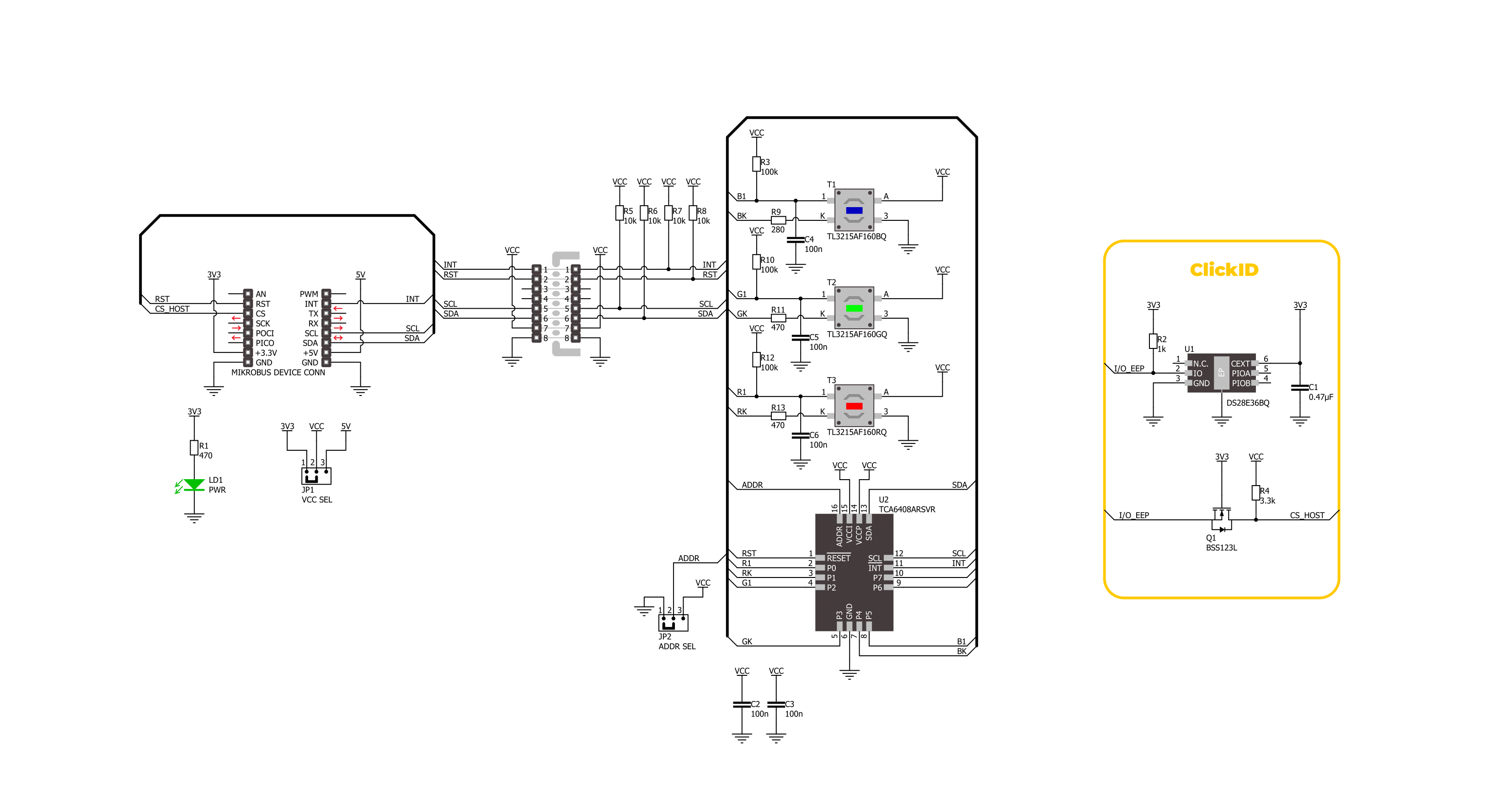
Button 3 Click is based on three tactile switches, members of the TL3215 series of tactile switches from E-Switch. Each specific switch features several key characteristics, denoted by its part number TL3215AF160BQ/TL3215AF160RQ/TL3215AF160GQ. The 'TL' in the part number indicates it belongs to the TL series, known for its high reliability and consistent performance. The '3215' model is a testament to its robust construction and design. It includes an actuator option ('A') with a 2mm actuator, ensuring precise and responsive operation. The 'F160' denotes an actuation force of 160gf, providing a balanced tactile feedback that is neither too hard nor too soft, thus preventing accidental presses while remaining user-friendly. The 'B/R/G' indicates the blue/red/green color of the switch, making it easily identifiable, while the 'Q' signifies the use of silver contact material, known for its excellent conductivity and durability. Regarding specifications, these switches have an impressive electrical rating of 50mA at 12VDC, and their electrical and mechanical life is
rated at 1,000,000 cycles, ensuring longevity and reliability in various applications. Initially, the contact resistance is a maximum of 100mΩ, while the insulation resistance stands at 100MΩ at 500VDC, highlighting its excellent electrical isolation properties. The switches also have a dielectric strength of 250VAC for 1 minute and operate efficiently from -40°C to 85°C. The contact arrangement is single-pole single-throw (SPST), providing straightforward switching functionality. Additionally, the integrated LED in this version operates at a forward current of 20mA with a typical forward voltage of 3V at 20mA. It delivers a typical luminous intensity of 100mcd, ensuring clear visibility of the switch's status. This Click board™ is designed in a unique format supporting the newly introduced MIKROE feature called "Click Snap." Unlike the standardized version of Click boards, this feature allows the main sensor area to become movable by breaking the PCB, opening up many new possibilities for implementation. Thanks to the Snap feature, the switches can operate autonomously by accessing their signals directly on
the pins marked 1-8. Additionally, the Snap part includes a specified and fixed screw hole position, enabling users to secure the Snap board in their desired location. Button 3 Click communicates with the host MCU via the TCA6408A port expander using the I2C interface. This port expander allows control of all buttons and their control signals, including a signal dedicated to detecting button presses (providing an interrupt signal to the host MCU (INT) whenever the tactile switch is activated) and the signal that controls the LED on the TL3215. In addition to the I2C interface pins, the port expander also uses a reset (RST) pin and a jumper for I2C address selection, ADDR SEL. This Click board™ can operate with either 3.3V or 5V logic voltage levels selected via the VCC SEL jumper. This way, both 3.3V and 5V capable MCUs can use the communication lines properly. Also, this Click board™ comes equipped with a library containing easy-to-use functions and an example code that can be used as a reference for further development.

Features overview
Development board
Curiosity PIC32 MZ EF development board is a fully integrated 32-bit development platform featuring the high-performance PIC32MZ EF Series (PIC32MZ2048EFM) that has a 2MB Flash, 512KB RAM, integrated FPU, Crypto accelerator, and excellent connectivity options. It includes an integrated programmer and debugger, requiring no additional hardware. Users can expand
functionality through MIKROE mikroBUS™ Click™ adapter boards, add Ethernet connectivity with the Microchip PHY daughter board, add WiFi connectivity capability using the Microchip expansions boards, and add audio input and output capability with Microchip audio daughter boards. These boards are fully integrated into PIC32’s powerful software framework, MPLAB Harmony,
which provides a flexible and modular interface to application development a rich set of inter-operable software stacks (TCP-IP, USB), and easy-to-use features. The Curiosity PIC32 MZ EF development board offers expansion capabilities making it an excellent choice for a rapid prototyping board in Connectivity, IOT, and general-purpose applications.

Microcontroller Overview
MCU Card / MCU

Architecture
PIC32
MCU Memory (KB)
2048
Silicon Vendor
Microchip
Pin count
100
RAM (Bytes)
524288
Used MCU Pins
mikroBUS™ mapper
Take a closer look
Click board™ Schematic
Step by step
Project assembly

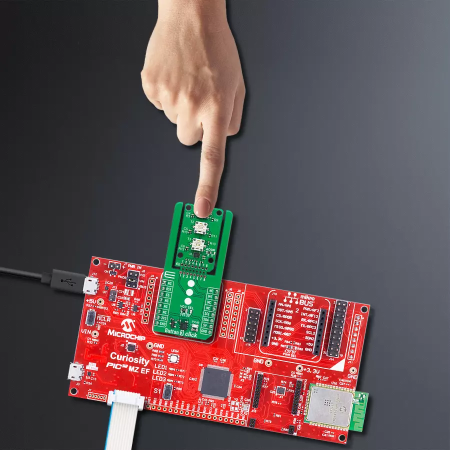
Start by selecting your development board and Click board™. Begin with the Curiosity PIC32 MZ EF as your development board.


Software Support
Library Description
This library contains API for Button 3 Click driver.
Key functions:
button3_toggle_red_led- This function toggles the red button LED by toggling the RK pin logic state.button3_toggle_green_led- This function toggles the green button LED by toggling the GK pin logic state.button3_toggle_blue_led- This function toggles the blue button LED by toggling the BK pin logic state.
Open Source
Code example
The complete application code and a ready-to-use project are available through the NECTO Studio Package Manager for direct installation in the NECTO Studio. The application code can also be found on the MIKROE GitHub account.
/*!
 * @file main.c
 * @brief Button 3 Click example
 *
 * # Description
 * This example demonstrates the use of Button 3 Click board by toggling a button
 * LED and its switch state on a button press.
 *
 * The demo application is composed of two sections :
 *
 * ## Application Init
 * Initializes the driver and performs the Click default configuration.
 *
 * ## Application Task
 * Toggles a button LED and its switch state on a button press and displays the state
 * on the USB UART.
 *
 * @author Stefan Filipovic
 *
 */

#include "board.h"
#include "log.h"
#include "button3.h"

static button3_t button3;
static log_t logger;

void application_init ( void )
{
    log_cfg_t log_cfg;  /**< Logger config object. */
    button3_cfg_t button3_cfg;  /**< Click config object. */

    /**
     * Logger initialization.
     * Default baud rate: 115200
     * Default log level: LOG_LEVEL_DEBUG
     * @note If USB_UART_RX and USB_UART_TX
     * are defined as HAL_PIN_NC, you will
     * need to define them manually for log to work.
     * See @b LOG_MAP_USB_UART macro definition for detailed explanation.
     */
    LOG_MAP_USB_UART( log_cfg );
    log_init( &logger, &log_cfg );
    log_info( &logger, " Application Init " );

    // Click initialization.
    button3_cfg_setup( &button3_cfg );
    BUTTON3_MAP_MIKROBUS( button3_cfg, MIKROBUS_1 );
    if ( I2C_MASTER_ERROR == button3_init( &button3, &button3_cfg ) )
    {
        log_error( &logger, " Communication init." );
        for ( ; ; );
    }

    if ( BUTTON3_ERROR == button3_default_cfg ( &button3 ) )
    {
        log_error( &logger, " Default configuration." );
        for ( ; ; );
    }

    log_info( &logger, " Application Task " );
    log_printf ( &logger, " Press button to change switch state\r\n\n" );
    log_printf ( &logger, " RED SWITCH OFF\r\n\n" );
    log_printf ( &logger, " GREEN SWITCH OFF\r\n\n" );
    log_printf ( &logger, " BLUE SWITCH OFF\r\n\n" );
}

void application_task ( void )
{
    static uint8_t red_switch_state = BUTTON3_SWITCH_OFF;
    static uint8_t green_switch_state = BUTTON3_SWITCH_OFF;
    static uint8_t blue_switch_state = BUTTON3_SWITCH_OFF;
    uint8_t switch_state = BUTTON3_SWITCH_OFF;

    if ( BUTTON3_PIN_STATE_LOW == button3_get_int_pin ( &button3 ) )
    {
        if ( ( BUTTON3_OK == button3_get_red_button ( &button3, &switch_state ) ) &&
             ( BUTTON3_BUTTON_PRESSED == switch_state ) )
        {
            button3_toggle_red_led ( &button3 );
            red_switch_state ^= BUTTON3_SWITCH_ON;
            if ( BUTTON3_SWITCH_ON == red_switch_state )
            {
                log_printf ( &logger, " RED SWITCH ON\r\n\n" );
            }
            else
            {
                log_printf ( &logger, " RED SWITCH OFF\r\n\n" );
            }
        }
        if ( ( BUTTON3_OK == button3_get_green_button ( &button3, &switch_state ) ) &&
             ( BUTTON3_BUTTON_PRESSED == switch_state ) )
        {
            button3_toggle_green_led ( &button3 );
            green_switch_state ^= BUTTON3_SWITCH_ON;
            if ( BUTTON3_SWITCH_ON == green_switch_state )
            {
                log_printf ( &logger, " GREEN SWITCH ON\r\n\n" );
            }
            else
            {
                log_printf ( &logger, " GREEN SWITCH OFF\r\n\n" );
            }
        }
        if ( ( BUTTON3_OK == button3_get_blue_button ( &button3, &switch_state ) ) &&
             ( BUTTON3_BUTTON_PRESSED == switch_state ) )
        {
            button3_toggle_blue_led ( &button3 );
            blue_switch_state ^= BUTTON3_SWITCH_ON;
            if ( BUTTON3_SWITCH_ON == blue_switch_state )
            {
                log_printf ( &logger, " BLUE SWITCH ON\r\n\n" );
            }
            else
            {
                log_printf ( &logger, " BLUE SWITCH OFF\r\n\n" );
            }
        }
        Delay_ms ( 100 );
    }
}

int main ( void )
{
    /* Do not remove this line or clock might not be set correctly. */
    #ifdef PREINIT_SUPPORTED
    preinit();
    #endif

    application_init( );

    for ( ; ; )
    {
        application_task( );
    }

    return 0;
}

// ------------------------------------------------------------------------ END
Additional Support
Resources
Category:Pushbutton/Switches


