Make your thermal monitor using STS31-DIS and PIC32MX534F064H
Your temperature experts!
Published Feb 25, 2023
Click board™
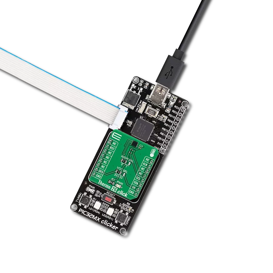
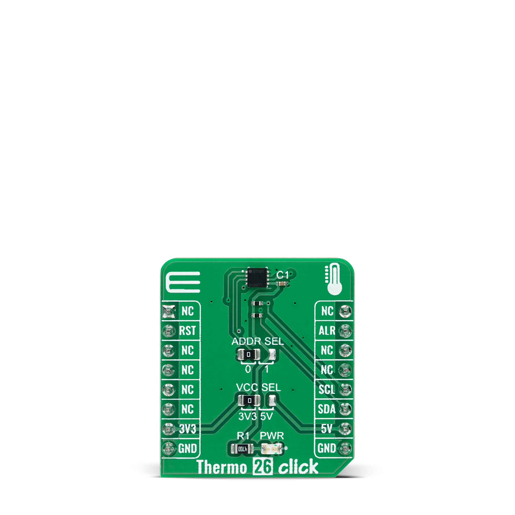
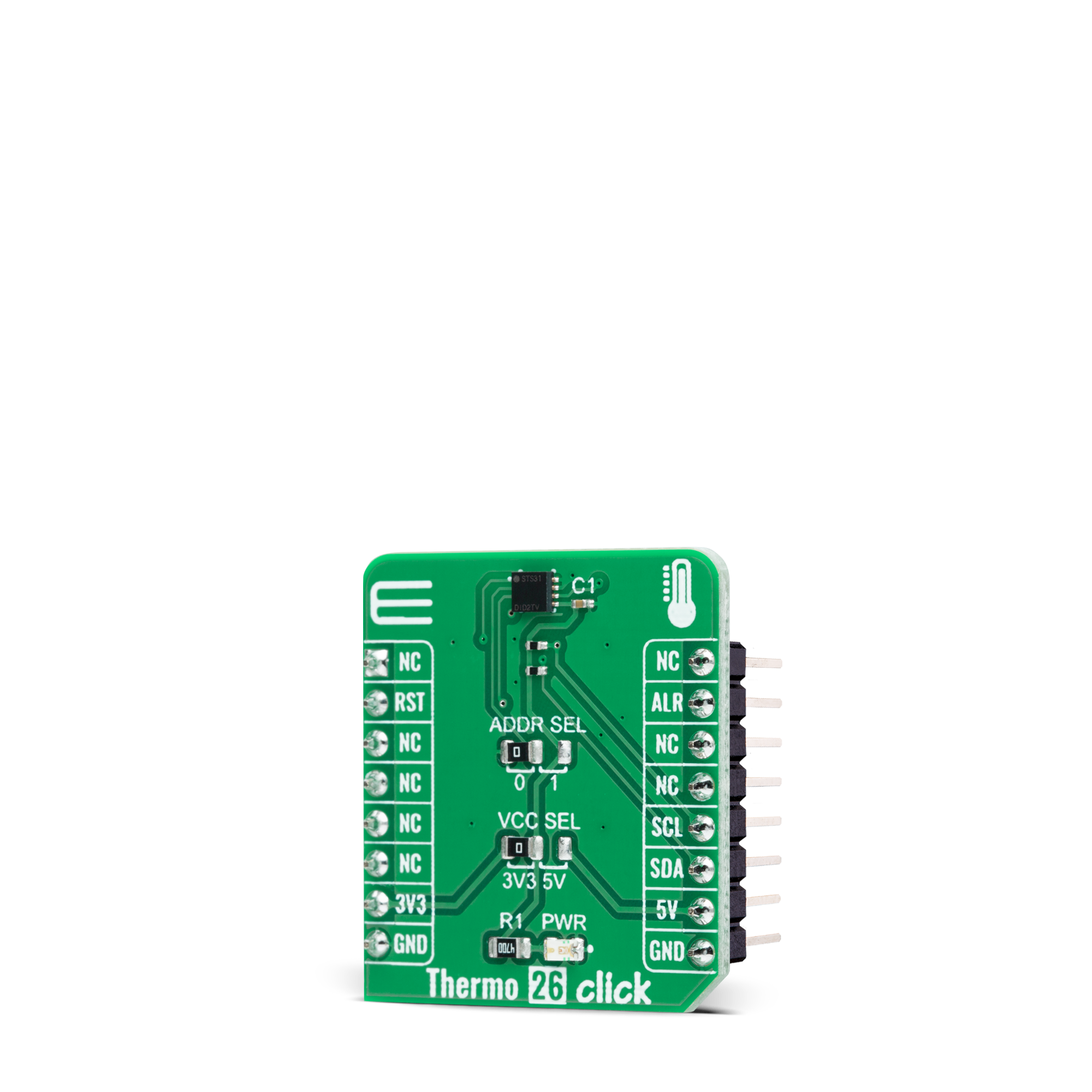
Thermo 26 Click
Dev. board
PIC32MX clicker
Compiler
NECTO Studio
MCU
PIC32MX534F064H
Undoubtedly the best choice for highly accurate temperature measurements
A
A
Hardware Overview
How does it work?
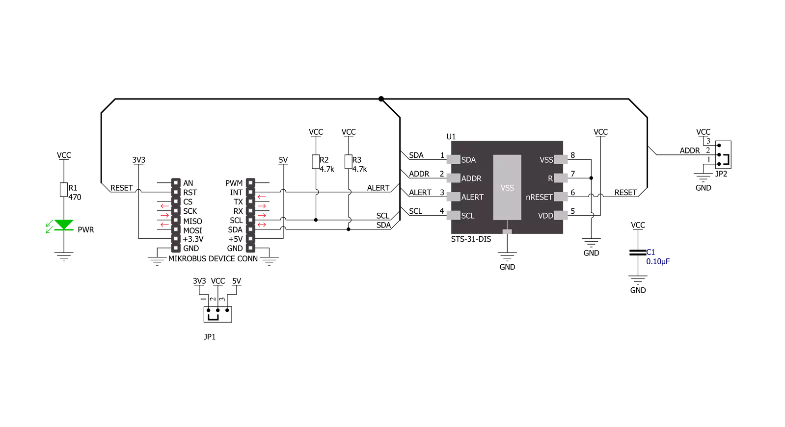
Thermo 26 Click is based on the STS31-DIS, a digital temperature sensor from Sensirion with increased intelligence, reliability, NIST traceability, and improved accuracy specifications utilizing the industry-proven CMOSens® Technology. It integrates a digital temperature sensor with a 16-bit analog-to-digital converter (ADC), a data processing circuit, and serial interface logic functions in one package. The voltage is digitized and converted to a 16-bit temperature result in degrees Celsius, with a resolution of 0.01°C. The STS31-DIS temperature sensor gives a fully calibrated, linearized, and supply-voltage-
compensated digital output with outstanding accuracy of up to ±0.2°C typical over a temperature range of 0°C to 90°C. Thermo 26 Click communicates with an MCU using the standard I2C 2-Wire interface to read data and configure settings, supporting Fast Mode Plus up to 1MHz. Also, the STS31-DIS allows choosing the least significant bit (LSB) of its I2C slave address using the SMD jumper labeled ADDR SEL. It also possesses an additional interrupt alert signal, routed on the INT pin of the mikroBUS™ socket labeled as ALT. The ALT pin indicates when a specific
interrupt event occurs, depending on the temperature reading value relative to programmable limits. The general reset function is routed on the RST pin of the mikroBUS™ socket. This Click board™ can operate with either 3.3V or 5V logic voltage levels selected via the VCC SEL jumper. This way, both 3.3V and 5V capable MCUs can use the communication lines properly. However, the Click board™ comes equipped with a library containing easy-to-use functions and an example code that can be used, as a reference, for further development.
Features overview
Development board
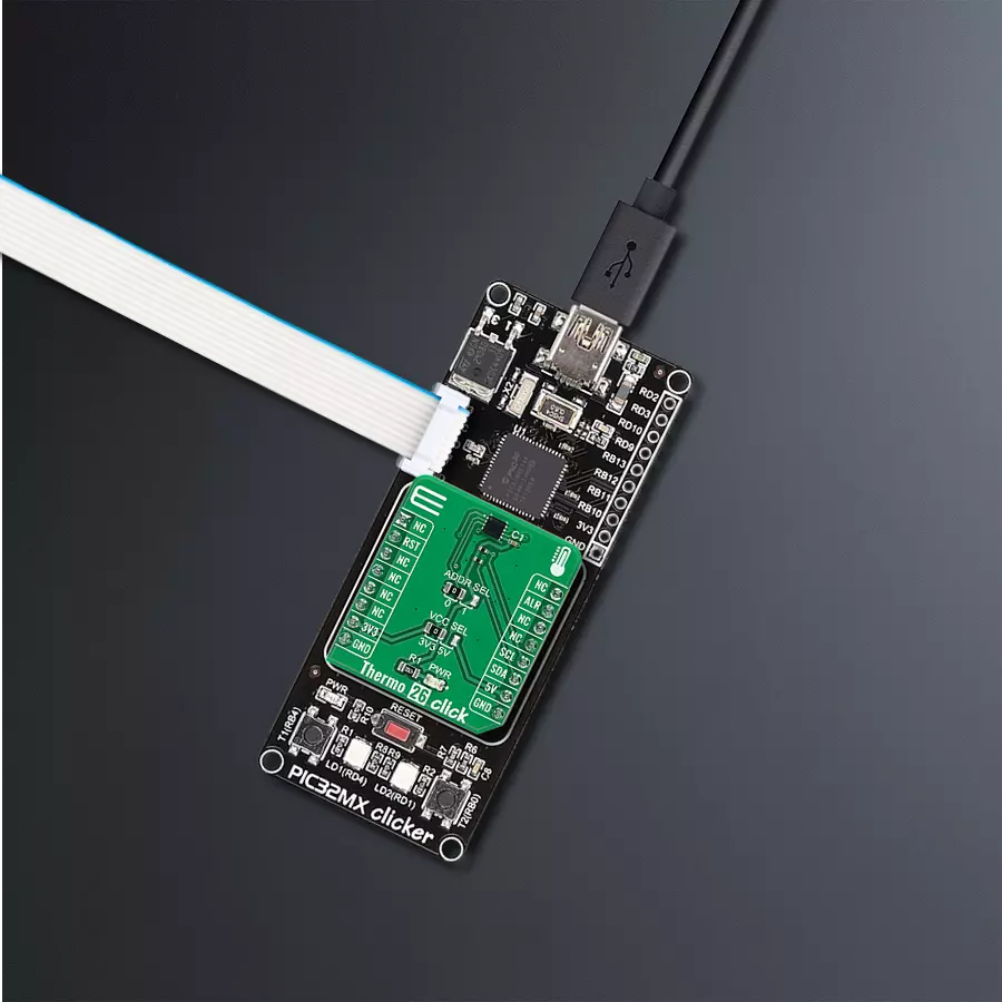
PIC32MX Clicker is a compact starter development board that brings the flexibility of add-on Click boards™ to your favorite microcontroller, making it a perfect starter kit for implementing your ideas. It comes with an onboard 32-bit PIC32 microcontroller, the PIC32MX534F064H from Microchip, a USB connector, LED indicators, buttons, a mikroProg connector, and a header for interfacing with external electronics. Thanks to its compact design with clear and easy-recognizable silkscreen markings, it provides a fluid and immersive working experience, allowing access
anywhere and under any circumstances. Each part of the PIC32MX Clicker development kit contains the components necessary for the most efficient operation of the same board. In addition to the possibility of choosing the PIC32MX Clicker programming method, using USB HID mikroBootloader, or through an external mikroProg connector for PIC, dsPIC, or PIC32 programmer, the Clicker board also includes a clean and regulated power supply module for the development kit. The USB Mini-B connection can provide up to 500mA of current, which is more
than enough to operate all onboard and additional modules. All communication methods that mikroBUS™ itself supports are on this board, including the well-established mikroBUS™ socket, reset button, and several buttons and LED indicators. PIC32MX Clicker is an integral part of the Mikroe ecosystem, allowing you to create a new application in minutes. Natively supported by Mikroe software tools, it covers many aspects of prototyping thanks to a considerable number of different Click boards™ (over a thousand boards), the number of which is growing every day.

Microcontroller Overview
MCU Card / MCU
Architecture
PIC32
MCU Memory (KB)
64
Silicon Vendor
Microchip
Pin count
64
RAM (Bytes)
16384
Used MCU Pins
mikroBUS™ mapper
Take a closer look
Click board™ Schematic
Step by step
Project assembly

Start by selecting your development board and Click board™. Begin with the PIC32MX clicker as your development board.


Software Support
Library Description
This library contains API for Thermo 26 Click driver.
Key functions:
thermo26_read_serial_numThis function reads the 32-bit unique serial number.thermo26_start_measurementThis function starts the measurements by sending the specified command.thermo26_read_temperatureThis function reads the temperature raw data measurements and converts them to degrees Celsius.
Open Source
Code example
The complete application code and a ready-to-use project are available through the NECTO Studio Package Manager for direct installation in the NECTO Studio. The application code can also be found on the MIKROE GitHub account.
/*!
 * @file main.c
 * @brief Thermo 26 Click example
 *
 * # Description
 * This example demonstrates the use of Thermo 26 Click board by reading and displaying
 * the temperature measurements.
 *
 * The demo application is composed of two sections :
 *
 * ## Application Init
 * Initializes the driver and resets the device, and after that reads the serial number and
 * starts the periodic measurements at 2 mps with high repeatability.
 *
 * ## Application Task
 * Reads the temperature measurement in degrees Celsius and displays the results on the USB UART
 * approximately once per second.
 *
 * @author Stefan Filipovic
 *
 */

#include "board.h"
#include "log.h"
#include "thermo26.h"

static thermo26_t thermo26;
static log_t logger;

void application_init ( void )
{
    log_cfg_t log_cfg;  /**< Logger config object. */
    thermo26_cfg_t thermo26_cfg;  /**< Click config object. */

    /**
     * Logger initialization.
     * Default baud rate: 115200
     * Default log level: LOG_LEVEL_DEBUG
     * @note If USB_UART_RX and USB_UART_TX
     * are defined as HAL_PIN_NC, you will
     * need to define them manually for log to work.
     * See @b LOG_MAP_USB_UART macro definition for detailed explanation.
     */
    LOG_MAP_USB_UART( log_cfg );
    log_init( &logger, &log_cfg );
    log_info( &logger, " Application Init " );

    // Click initialization.
    thermo26_cfg_setup( &thermo26_cfg );
    THERMO26_MAP_MIKROBUS( thermo26_cfg, MIKROBUS_1 );
    if ( I2C_MASTER_ERROR == thermo26_init( &thermo26, &thermo26_cfg ) )
    {
        log_error( &logger, " Communication init." );
        for ( ; ; );
    }

    thermo26_reset_device ( &thermo26 );

    uint32_t serial_num;
    if ( THERMO26_ERROR == thermo26_read_serial_num ( &thermo26, &serial_num ) )
    {
        log_error( &logger, " Read serial number." );
        for ( ; ; );
    }
    log_printf ( &logger, " Serial number: 0x%.8LX\r\n", serial_num );

    if ( THERMO26_ERROR == thermo26_start_measurement ( &thermo26, THERMO26_CMD_PERIODIC_2_MPS_REP_HIGH ) )
    {
        log_error( &logger, " Start measurement." );
        for ( ; ; );
    }

    log_info( &logger, " Application Task " );
}

void application_task ( void )
{
    float temperature;
    if ( THERMO26_OK == thermo26_read_temperature ( &thermo26, &temperature ) )
    {
        log_printf ( &logger, " Temperature: %.2f\r\n\n", temperature );
    }
    Delay_ms ( 1000 );
}

int main ( void )
{
    /* Do not remove this line or clock might not be set correctly. */
    #ifdef PREINIT_SUPPORTED
    preinit();
    #endif

    application_init( );

    for ( ; ; )
    {
        application_task( );
    }

    return 0;
}

// ------------------------------------------------------------------------ END
Additional Support
Resources
Category:Temperature & humidity


