Obtain real-time temperature data for various purposes with EMC1414 and PIC18LF45K42
Temperature insight made simple

Published Nov 02, 2023
Click board™
THERMO 5 Click
Dev. board
EasyPIC v8
Compiler
NECTO Studio
MCU
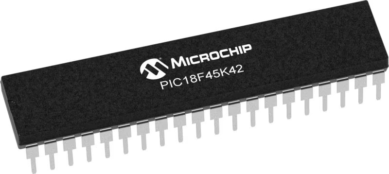
PIC18LF45K42
From industrial processes to everyday applications, our temperature measurement solution offers a reliable and adaptable way to measure temperature in diverse settings
A
A
Hardware Overview
How does it work?
Thermo 5 Click is based on the EMC1414, a multiple-channel temperature sensor with beta compensation from Microchip. It features resistance error correction (REC), beta compensation that supports CPU diodes requiring the BJT/transistor models, and, above all, an automatic diode-type detection, which provides a robust solution for complex environmental monitoring applications. The device contains programmable High, Low, and Thermo limits for all measured temperature channels. If the measured temperature goes below the Low limit or above the High limit, the ALERT pin can be
asserted (based on user settings). If the measured temperature meets or exceeds the Thermo Limit, the output pin is asserted unconditionally, providing two tiers of temperature detection. Thermo 5 Click uses a 2-Wire SMBus communication protocol with the host MCU. It has a programmable SMBus address. By setting the INT SEL jumper, you can choose the interrupts from the THM and ALT, which stands for Therm and Alert (the THM is set by default). This way, whenever any of the measured temperatures exceeds programmed limits, the output is asserted. The Alert mode has an interrupt and a
comparator mode of operation. The interrupt mode asserts the output if a faulty diode or out-of-limit measurement is detected. In comparator mode, the output pin will be asserted if the measured temperatures exceed the respective high limit. This Click board™ can be operated only with a 3.3V logic voltage level. The board must perform appropriate logic voltage level conversion before using MCUs with different logic levels. Also, this Click board™ comes equipped with a library containing easy-to-use functions and an example code that can be used as a reference for further development.


Features overview
Development board
EasyPIC v8 is a development board specially designed for the needs of rapid development of embedded applications. It supports many high pin count 8-bit PIC microcontrollers from Microchip, regardless of their number of pins, and a broad set of unique functions, such as the first-ever embedded debugger/programmer. The development board is well organized and designed so that the end-user has all the necessary elements, such as switches, buttons, indicators, connectors, and others, in one place. Thanks to innovative manufacturing technology, EasyPIC v8 provides a fluid and immersive working experience, allowing access anywhere and under any
circumstances at any time. Each part of the EasyPIC v8 development board contains the components necessary for the most efficient operation of the same board. In addition to the advanced integrated CODEGRIP programmer/debugger module, which offers many valuable programming/debugging options and seamless integration with the Mikroe software environment, the board also includes a clean and regulated power supply module for the development board. It can use a wide range of external power sources, including a battery, an external 12V power supply, and a power source via the USB Type-C (USB-C) connector.
Communication options such as USB-UART, USB DEVICE, and CAN are also included, including the well-established mikroBUS™ standard, two display options (graphical and character-based LCD), and several different DIP sockets. These sockets cover a wide range of 8-bit PIC MCUs, from the smallest PIC MCU devices with only eight up to forty pins. EasyPIC v8 is an integral part of the Mikroe ecosystem for rapid development. Natively supported by Mikroe software tools, it covers many aspects of prototyping and development thanks to a considerable number of different Click boards™ (over a thousand boards), the number of which is growing every day.

Microcontroller Overview
MCU Card / MCU
Architecture
PIC
MCU Memory (KB)
32
Silicon Vendor
Microchip
Pin count
40
RAM (Bytes)
2048
Used MCU Pins
mikroBUS™ mapper
Take a closer look
Click board™ Schematic

Step by step
Project assembly

Start by selecting your development board and Click board™. Begin with the EasyPIC v8 as your development board.


Track your results in real time
Application Output
1. Application Output - In Debug mode, the 'Application Output' window enables real-time data monitoring, offering direct insight into execution results. Ensure proper data display by configuring the environment correctly using the provided tutorial.

2. UART Terminal - Use the UART Terminal to monitor data transmission via a USB to UART converter, allowing direct communication between the Click board™ and your development system. Configure the baud rate and other serial settings according to your project's requirements to ensure proper functionality. For step-by-step setup instructions, refer to the provided tutorial.

3. Plot Output - The Plot feature offers a powerful way to visualize real-time sensor data, enabling trend analysis, debugging, and comparison of multiple data points. To set it up correctly, follow the provided tutorial, which includes a step-by-step example of using the Plot feature to display Click board™ readings. To use the Plot feature in your code, use the function: plot(*insert_graph_name*, variable_name);. This is a general format, and it is up to the user to replace 'insert_graph_name' with the actual graph name and 'variable_name' with the parameter to be displayed.

Software Support
Library Description
This library contains API for THERMO 5 Click driver.
Key functions:
thermo5_read_inter_temp- This function reads measurements made by internal diode.thermo5_read_extern_1_temp- This function reads measurements made by external 1 diode.thermo5_read_high_limit_stat- This function reads the High Limit Status register which utilises its lower nibble to represents which diodes have exceed their programmed high limit.
Open Source
Code example
The complete application code and a ready-to-use project are available through the NECTO Studio Package Manager for direct installation in the NECTO Studio. The application code can also be found on the MIKROE GitHub account.
/*!
 * \file
 * \brief THERMO5 Click example
 *
 * # Description
 * This app measures internal and external temperature.
 *
 * The demo application is composed of two sections :
 *
 * ## Application Init
 * Initalizes device.
 *
 * ## Application Task
 * This is an example that shows the most important functions that Thermo 5 Click has.
 *
 * \author MikroE Team
 *
 */
// ------------------------------------------------------------------- INCLUDES

#include "board.h"
#include "log.h"
#include "thermo5.h"

// ------------------------------------------------------------------ VARIABLES

static thermo5_t thermo5;
static log_t logger;

// ------------------------------------------------------ APPLICATION FUNCTIONS

void application_init ( void )
{
    log_cfg_t log_cfg;
    thermo5_cfg_t cfg;

    /**
     * Logger initialization.
     * Default baud rate: 115200
     * Default log level: LOG_LEVEL_DEBUG
     * @note If USB_UART_RX and USB_UART_TX
     * are defined as HAL_PIN_NC, you will
     * need to define them manually for log to work.
     * See @b LOG_MAP_USB_UART macro definition for detailed explanation.
     */
    LOG_MAP_USB_UART( log_cfg );
    log_init( &logger, &log_cfg );
    log_info( &logger, "---- Application Init ----" );

    //  Click initialization.

    thermo5_cfg_setup( &cfg );
    THERMO5_MAP_MIKROBUS( cfg, MIKROBUS_1 );
    thermo5_init( &thermo5, &cfg );
    Delay_ms ( 500 );
    log_printf( &logger, " Thermo 5 Click ready! \r\n" );
    log_printf( &logger, "-----------------------\r\n" );
    Delay_ms ( 100 );
}

void application_task ( void )
{
    float inter_temp;
    float exter_temp_1;
    float exter_temp_2;
    float exter_temp_3;

    inter_temp = thermo5_read_inter_temp( &thermo5 );
    log_printf( &logger, " Internal temperature :   %.2f \r\n", inter_temp );
    exter_temp_1 = thermo5_read_extern_1_temp( &thermo5 );
    log_printf( &logger, " External temperature 1 : %.2f \r\n", exter_temp_1 );
    exter_temp_2 = thermo5_read_extern_2_temp( &thermo5 );
    log_printf( &logger, " External temperature 2 : %.2f \r\n", exter_temp_2 );
    exter_temp_3 = thermo5_read_extern_3_temp( &thermo5 );
    log_printf( &logger, " External temperature 3 : %.2f \r\n", exter_temp_2 );
    log_printf( &logger, "---------------------------------\r\n" );
    Delay_ms ( 1000 );
    Delay_ms ( 1000 );
    Delay_ms ( 1000 );
    Delay_ms ( 1000 );
    Delay_ms ( 1000 );
}

int main ( void )
{
    /* Do not remove this line or clock might not be set correctly. */
    #ifdef PREINIT_SUPPORTED
    preinit();
    #endif

    application_init( );

    for ( ; ; )
    {
        application_task( );
    }

    return 0;
}

// ------------------------------------------------------------------------ END
Additional Support
Resources
Category:Temperature & humidity


