Achieve advanced proximity measurement with TMD2635 and ATmega324P
The dynamic duo for detecting your presence!
Published Apr 23, 2023
Click board™
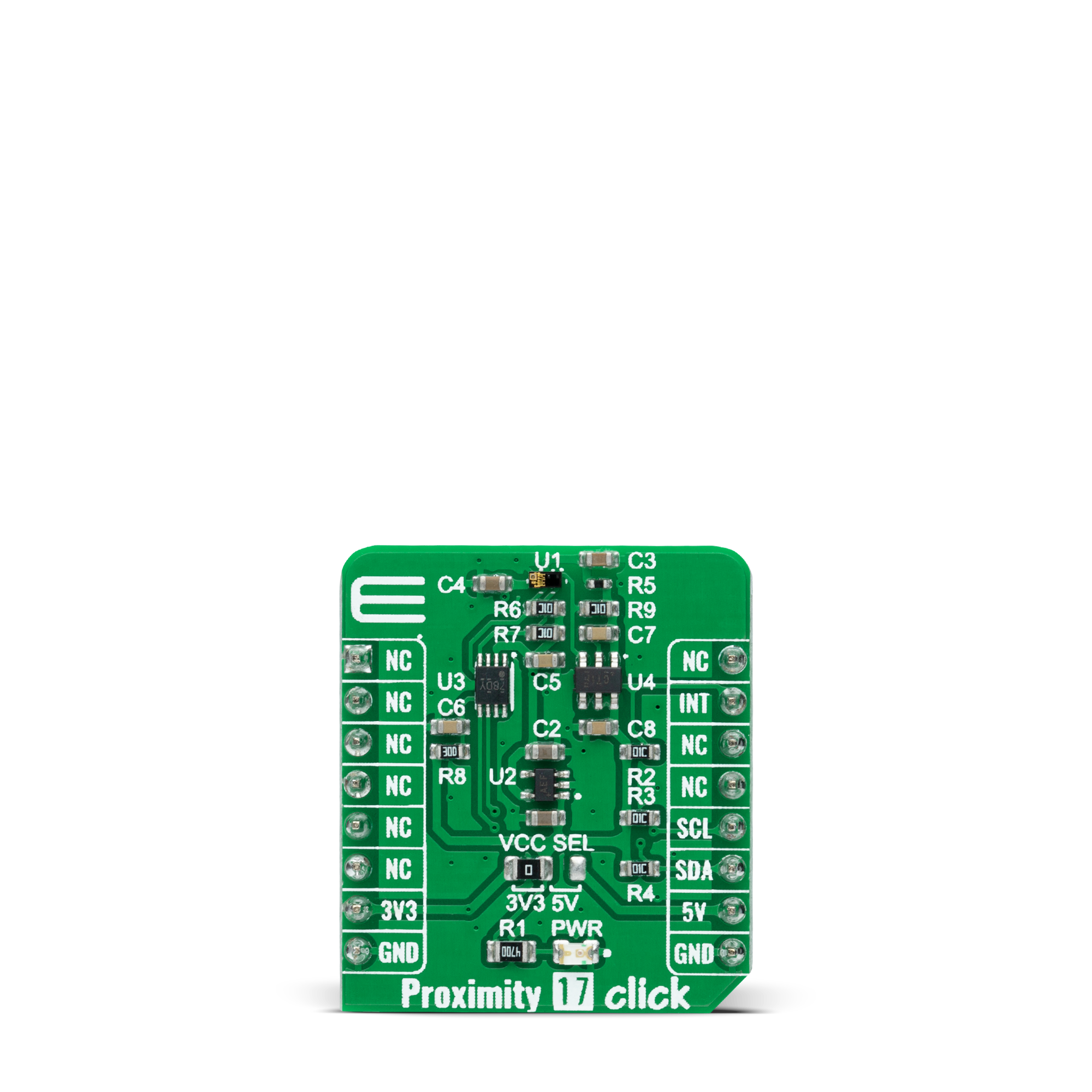
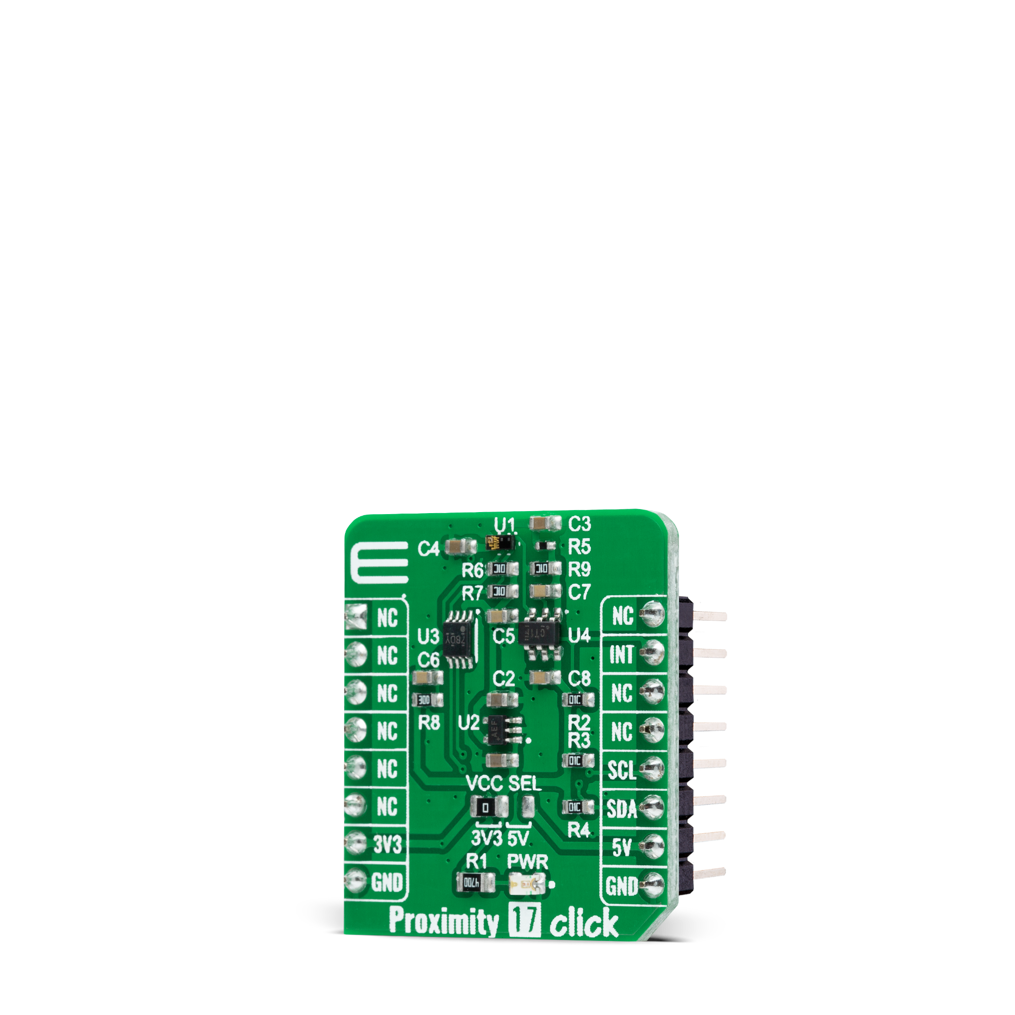
Proximity 17 Click
Dev. board
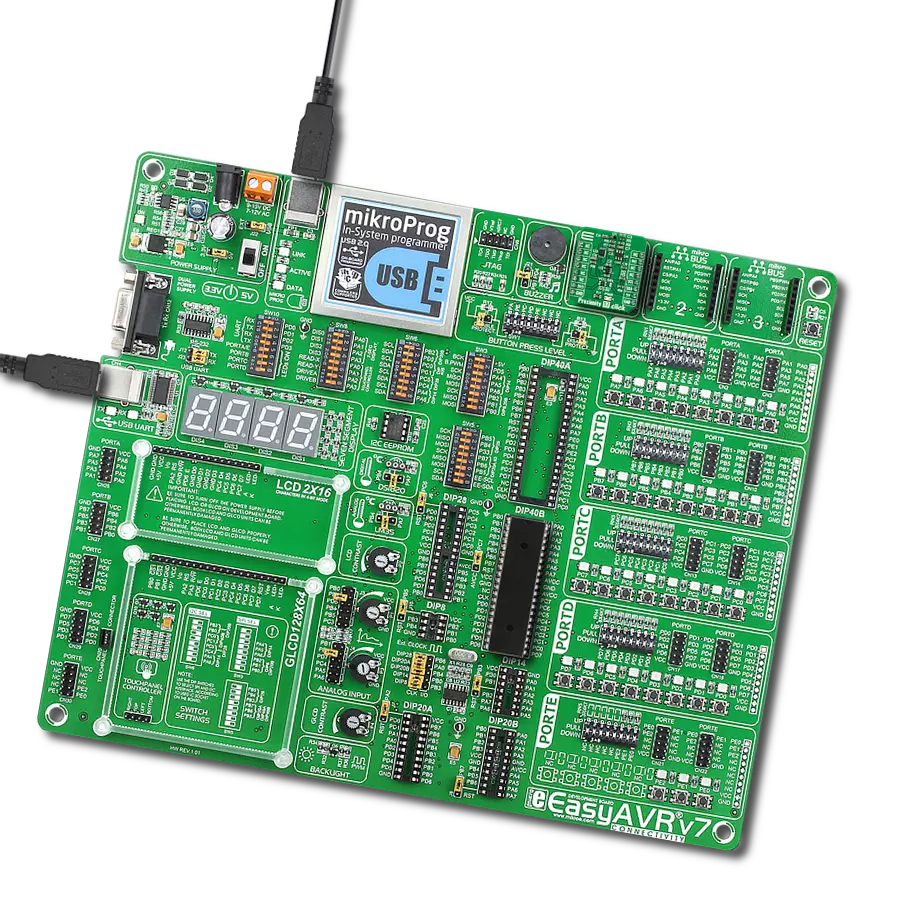
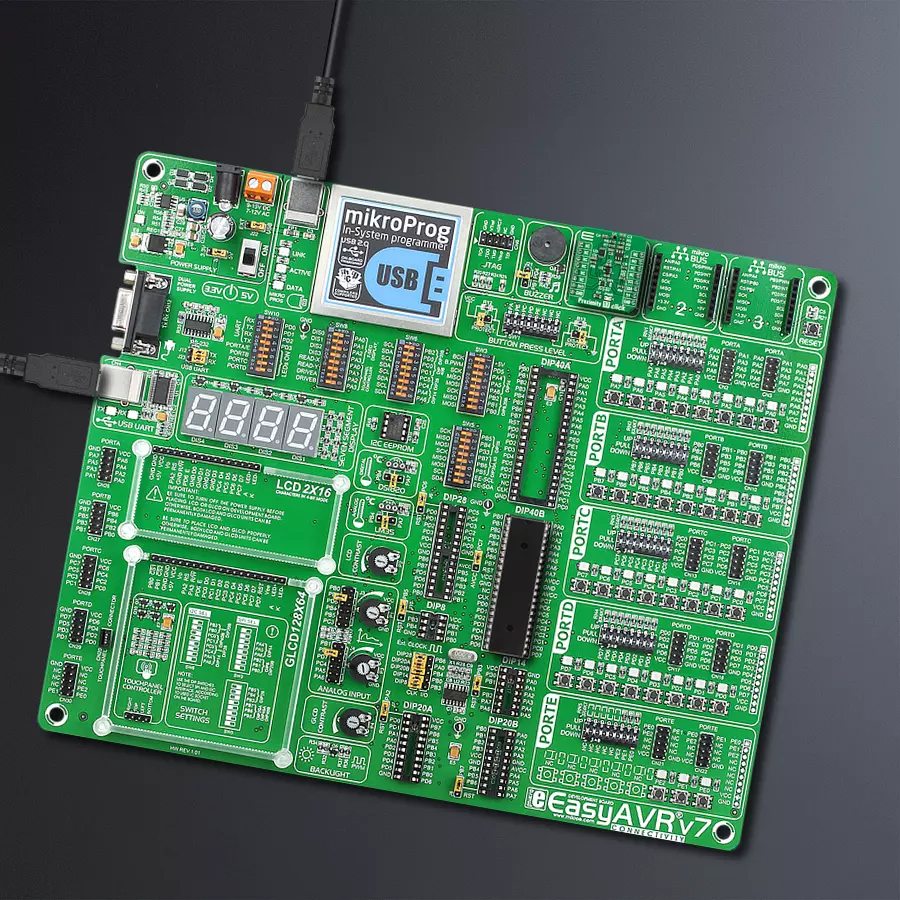
EasyAVR v7
Compiler
NECTO Studio
MCU
ATmega324P
Experience seamless and accurate detection of nearby objects with our state-of-the-art proximity solution, designed to enhance performance and safety in various applications
A
A
Hardware Overview
How does it work?
Proximity 17 Click is based on the TMD2635, a miniature close-range proximity sensor module from ams AG. The TMD2635 implements a 940nm infrared VCSEL (Vertical Cavity Surface Emitting Laser) factory calibrated for IR proximity response alongside a digital I2C serial interface. The proximity detection feature provides object detection (e.g., close proximity) by photodiode detection of reflected IR energy sourced by the integrated VCSEL emitter. The proximity engine also features a wide range offset adjustment to compensate for unwanted IR energy reflection at the sensor. The results are further improved by automatic ambient light subtraction. The TMD2635 does not require a specific Power-Up sequence but requires a supply
voltage of 1.8V to work correctly. Therefore, a small regulating LDO, the MAX8511, provides a 1.8V out of selected mikroBUS™ power rail. Also, it can be shut down through software with a low standby current, allowing the power rails to remain powered at all times. Proximity 17 Click communicates with MCU using the standard I2C 2-Wire interface with a maximum clock frequency of 400kHz, fully adjustable through software registers with a 14-bit proximity result stored in a PDATA register. Since the sensor for operation requires a power supply of 1.8V, this Click board™ also features the PCA9306 and SN74LVC1T45 voltage-level translators. The I2C interface bus lines are routed to the voltage-level translators allowing this Click board™
to work with both 3.3V and 5V MCUs properly. Also, it uses an interrupt pin, the INT pin of the mikroBUS™ socket, used when an interrupt occurs to alert the system when proximity result crosses upper or lower threshold settings. This Click board™ can operate with either 3.3V or 5V logic voltage levels selected via the VCC SEL jumper. This way, both 3.3V and 5V capable MCUs can use the communication lines properly. However, the Click board™ comes equipped with a library containing easy-to-use functions and an example code that can be used, as a reference, for further development.
Features overview
Development board
EasyAVR v7 is the seventh generation of AVR development boards specially designed for the needs of rapid development of embedded applications. It supports a wide range of 16-bit AVR microcontrollers from Microchip and has a broad set of unique functions, such as a powerful onboard mikroProg programmer and In-Circuit debugger over USB. The development board is well organized and designed so that the end-user has all the necessary elements in one place, such as switches, buttons, indicators, connectors, and others. With four different connectors for each port, EasyAVR v7 allows you to connect accessory boards, sensors, and custom electronics more
efficiently than ever. Each part of the EasyAVR v7 development board contains the components necessary for the most efficient operation of the same board. An integrated mikroProg, a fast USB 2.0 programmer with mikroICD hardware In-Circuit Debugger, offers many valuable programming/debugging options and seamless integration with the Mikroe software environment. Besides it also includes a clean and regulated power supply block for the development board. It can use a wide range of external power sources, including an external 12V power supply, 7-12V AC or 9-15V DC via DC connector/screw terminals, and a power source via the USB Type-B (USB-B)
connector. Communication options such as USB-UART and RS-232 are also included, alongside the well-established mikroBUS™ standard, three display options (7-segment, graphical, and character-based LCD), and several different DIP sockets which cover a wide range of 16-bit AVR MCUs. EasyAVR v7 is an integral part of the Mikroe ecosystem for rapid development. Natively supported by Mikroe software tools, it covers many aspects of prototyping and development thanks to a considerable number of different Click boards™ (over a thousand boards), the number of which is growing every day.

Microcontroller Overview
MCU Card / MCU

Architecture
AVR
MCU Memory (KB)
32
Silicon Vendor
Microchip
Pin count
40
RAM (Bytes)
2048
Used MCU Pins
mikroBUS™ mapper
Take a closer look
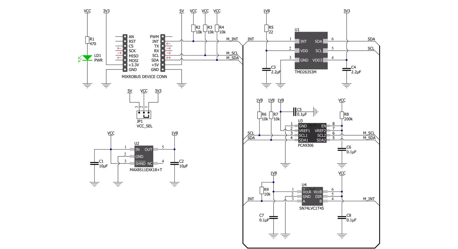
Click board™ Schematic
Step by step
Project assembly

Start by selecting your development board and Click board™. Begin with the EasyAVR v7 as your development board.


Track your results in real time
Application Output
1. Application Output - In Debug mode, the 'Application Output' window enables real-time data monitoring, offering direct insight into execution results. Ensure proper data display by configuring the environment correctly using the provided tutorial.

2. UART Terminal - Use the UART Terminal to monitor data transmission via a USB to UART converter, allowing direct communication between the Click board™ and your development system. Configure the baud rate and other serial settings according to your project's requirements to ensure proper functionality. For step-by-step setup instructions, refer to the provided tutorial.

3. Plot Output - The Plot feature offers a powerful way to visualize real-time sensor data, enabling trend analysis, debugging, and comparison of multiple data points. To set it up correctly, follow the provided tutorial, which includes a step-by-step example of using the Plot feature to display Click board™ readings. To use the Plot feature in your code, use the function: plot(*insert_graph_name*, variable_name);. This is a general format, and it is up to the user to replace 'insert_graph_name' with the actual graph name and 'variable_name' with the parameter to be displayed.

Software Support
Library Description
This library contains API for Proximity 17 Click driver.
Key functions:
proximity17_get_int_pinThis function returns the INT pin logic state.proximity17_read_proximityThis function reads the raw proximity data. The higher the value, the closer the detected object is.proximity17_soft_resetThis function executes the device software reset command.
Open Source
Code example
The complete application code and a ready-to-use project are available through the NECTO Studio Package Manager for direct installation in the NECTO Studio. The application code can also be found on the MIKROE GitHub account.
/*!
 * @file main.c
 * @brief Proximity17 Click example
 *
 * # Description
 * This example demonstrates the use of Proximity 17 Click board by reading and
 * displaying the proximity data on the USB UART.
 *
 * The demo application is composed of two sections :
 *
 * ## Application Init
 * Initializes the driver and logger, and performs the Click default configuration.
 *
 * ## Application Task
 * Reads the proximity data and displays it on the USB UART approximately once per second.
 * The higher the proximity value, the closer the detected object is.
 *
 * @author Stefan Filipovic
 *
 */

#include "board.h"
#include "log.h"
#include "proximity17.h"

static proximity17_t proximity17;
static log_t logger;

void application_init ( void )
{
    log_cfg_t log_cfg;  /**< Logger config object. */
    proximity17_cfg_t proximity17_cfg;  /**< Click config object. */

    /**
     * Logger initialization.
     * Default baud rate: 115200
     * Default log level: LOG_LEVEL_DEBUG
     * @note If USB_UART_RX and USB_UART_TX
     * are defined as HAL_PIN_NC, you will
     * need to define them manually for log to work.
     * See @b LOG_MAP_USB_UART macro definition for detailed explanation.
     */
    LOG_MAP_USB_UART( log_cfg );
    log_init( &logger, &log_cfg );
    log_info( &logger, " Application Init " );

    // Click initialization.
    proximity17_cfg_setup( &proximity17_cfg );
    PROXIMITY17_MAP_MIKROBUS( proximity17_cfg, MIKROBUS_1 );
    if ( I2C_MASTER_ERROR == proximity17_init( &proximity17, &proximity17_cfg ) )
    {
        log_error( &logger, " Communication init." );
        for ( ; ; );
    }

    if ( PROXIMITY17_ERROR == proximity17_default_cfg ( &proximity17 ) )
    {
        log_error( &logger, " Default configuration." );
        for ( ; ; );
    }

    log_info( &logger, " Application Task " );
}

void application_task ( void )
{
    uint16_t proximity;
    if ( PROXIMITY17_OK == proximity17_read_proximity ( &proximity17, &proximity ) )
    {
        log_printf ( &logger, " Proximity: %u\r\n\n", proximity );
        Delay_ms ( 1000 );
    }
}

int main ( void )
{
    /* Do not remove this line or clock might not be set correctly. */
    #ifdef PREINIT_SUPPORTED
    preinit();
    #endif

    application_init( );

    for ( ; ; )
    {
        application_task( );
    }

    return 0;
}

// ------------------------------------------------------------------------ END