Detect the presence of nearby objects without any physical contact with VCNL4200 and STM32F031K6
Embrace the future of proximity detection
Published Oct 01, 2024
Click board™
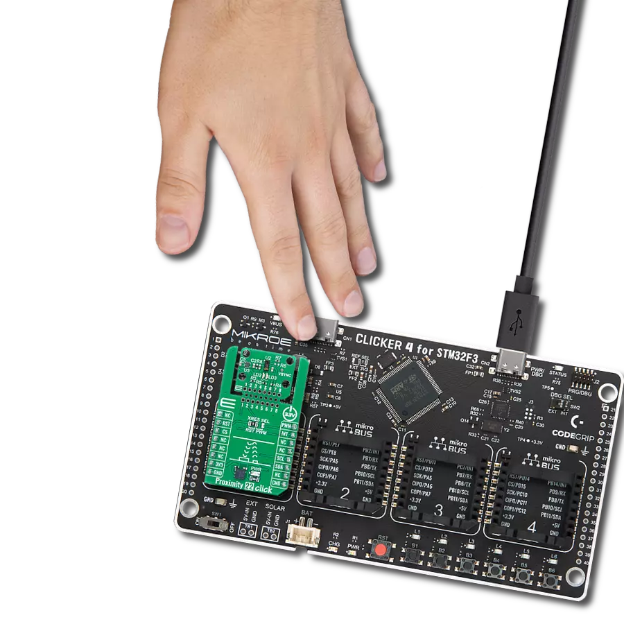
Proximity 3 Click
Dev. board
Nucleo 32 with STM32F031K6 MCU
Compiler
NECTO Studio
MCU
STM32F031K6
Our proximity detection solution aims to seamlessly integrate technology into your daily life, enhancing convenience and safety
A
A
Hardware Overview
How does it work?
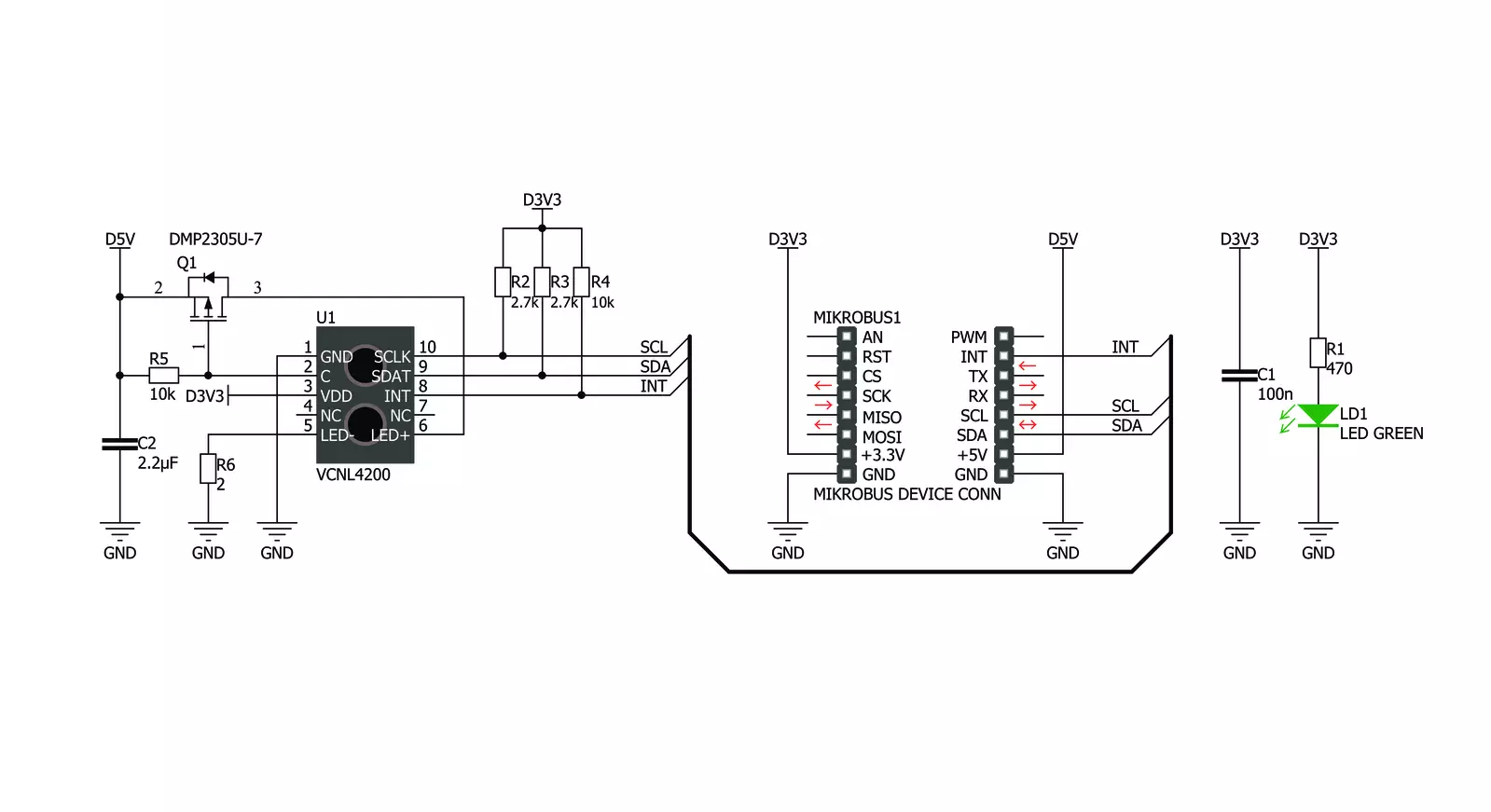
Proximity 3 Click is based on the VCNL4200 from Vishaywhich combines matched 940 nm IR emitter and a photodiode for proximity measurement and ambient light sensing. VCNL4200 offers programmable measurement by utilizing the advanced signal processing techniques, allowing the sensor to operate in various conditions. Communication with the microcontroller is done via the I2C interface so that the host controller can set the measurement parameters and request results back from the sensor. Both low and high threshold values for the measured property can also be set via the I2C so that the interrupts can be generated every time the threshold value is exceeded. This allows for the
reduced need of the sensor polling, which can result in better power management. With MikroElektronika library functions, setting up the registers is really easy and the tedious task of initializing the sensor is taken care of with a few simple function calls. More information about the sensor's registers and addresses can be found in the VCNL4200 datasheet. The Filtron™ technology used in the ALS, allows the sensor to match the ambient light spectral sensitivity to human eye response and it's immune to fluorescent light flicker. This ensures the accuracy of the measurements. The maximum detection range is selectable (197 / 393 / 786 / 1573 lux) with highest sensitivity 0.003 lux / step. The proximity sensor
uses advanced ambient and background light cancellation schemes, so it is fairly immune to interferences that might occur in this case. This allows for a quite precise proximity detection. The sensor can work either in 12-bit or 16-bit mode, selectable by I2C command. The click's range is up to 1.5m. VCNL4200 input voltage is 3V3, while the separate 5V supply rail is used to supply power for the IR emitter pulses, generated by the small external P-channel MOSFET (Q1). This way, the power dissipation of the IRED drive is displaced from the chip, and the high-current IRED drive pulses are isolated from the sensitive integrated circuit sections, connected to the 3V3 rail.


Features overview
Development board
Nucleo 32 with STM32F031K6 MCU board provides an affordable and flexible platform for experimenting with STM32 microcontrollers in 32-pin packages. Featuring Arduino™ Nano connectivity, it allows easy expansion with specialized shields, while being mbed-enabled for seamless integration with online resources. The
board includes an on-board ST-LINK/V2-1 debugger/programmer, supporting USB reenumeration with three interfaces: Virtual Com port, mass storage, and debug port. It offers a flexible power supply through either USB VBUS or an external source. Additionally, it includes three LEDs (LD1 for USB communication, LD2 for power,
and LD3 as a user LED) and a reset push button. The STM32 Nucleo-32 board is supported by various Integrated Development Environments (IDEs) such as IAR™, Keil®, and GCC-based IDEs like AC6 SW4STM32, making it a versatile tool for developers.

Microcontroller Overview
MCU Card / MCU

Architecture
ARM Cortex-M0
MCU Memory (KB)
32
Silicon Vendor
STMicroelectronics
Pin count
32
RAM (Bytes)
4096
You complete me!
Accessories
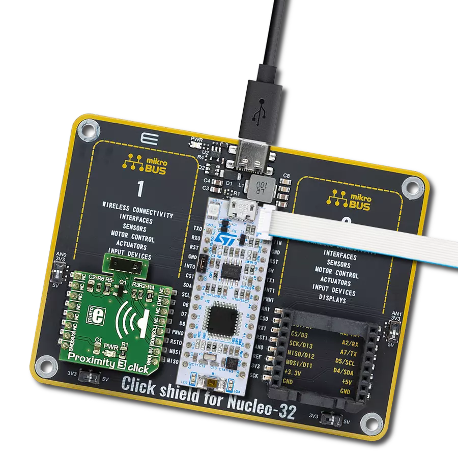
Click Shield for Nucleo-32 is the perfect way to expand your development board's functionalities with STM32 Nucleo-32 pinout. The Click Shield for Nucleo-32 provides two mikroBUS™ sockets to add any functionality from our ever-growing range of Click boards™. We are fully stocked with everything, from sensors and WiFi transceivers to motor control and audio amplifiers. The Click Shield for Nucleo-32 is compatible with the STM32 Nucleo-32 board, providing an affordable and flexible way for users to try out new ideas and quickly create prototypes with any STM32 microcontrollers, choosing from the various combinations of performance, power consumption, and features. The STM32 Nucleo-32 boards do not require any separate probe as they integrate the ST-LINK/V2-1 debugger/programmer and come with the STM32 comprehensive software HAL library and various packaged software examples. This development platform provides users with an effortless and common way to combine the STM32 Nucleo-32 footprint compatible board with their favorite Click boards™ in their upcoming projects.

Used MCU Pins
mikroBUS™ mapper
Take a closer look
Click board™ Schematic
Step by step
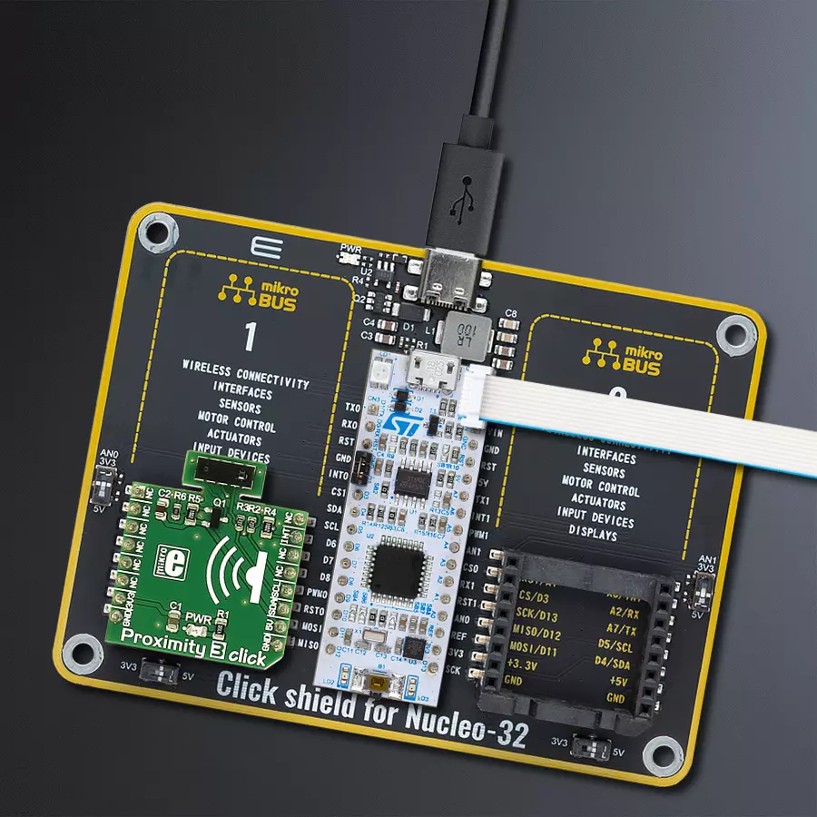
Project assembly

Start by selecting your development board and Click board™. Begin with the Nucleo 32 with STM32F031K6 MCU as your development board.


Track your results in real time
Application Output
1. Application Output - In Debug mode, the 'Application Output' window enables real-time data monitoring, offering direct insight into execution results. Ensure proper data display by configuring the environment correctly using the provided tutorial.

2. UART Terminal - Use the UART Terminal to monitor data transmission via a USB to UART converter, allowing direct communication between the Click board™ and your development system. Configure the baud rate and other serial settings according to your project's requirements to ensure proper functionality. For step-by-step setup instructions, refer to the provided tutorial.

3. Plot Output - The Plot feature offers a powerful way to visualize real-time sensor data, enabling trend analysis, debugging, and comparison of multiple data points. To set it up correctly, follow the provided tutorial, which includes a step-by-step example of using the Plot feature to display Click board™ readings. To use the Plot feature in your code, use the function: plot(*insert_graph_name*, variable_name);. This is a general format, and it is up to the user to replace 'insert_graph_name' with the actual graph name and 'variable_name' with the parameter to be displayed.

Software Support
Library Description
This library contains API for Proximity 3 Click driver.
Key functions:
proximity3_write_16- This function writes data to the desired registerproximity3_read_als- This function gets the data returned by the ambient light sensorproximity3_read_proximity- This function returns the proximity
Open Source
Code example
The complete application code and a ready-to-use project are available through the NECTO Studio Package Manager for direct installation in the NECTO Studio. The application code can also be found on the MIKROE GitHub account.
/*!
 * \file
 * \brief Proximity 3 Click example
 *
 * # Description
 * This application reads the raw ALS and proximity data from
 * Proximity 3 Click board.
 *
 * The demo application is composed of two sections :
 *
 * ## Application Init
 * Initializes the driver and performs the Click default configuration.
 *
 * ## Application Task
 * Reads the raw ALS and proximity data and displays the results on the USB UART
 * every 500ms.
 *
 * \author MikroE Team
 *
 */
// ------------------------------------------------------------------- INCLUDES

#include "board.h"
#include "log.h"
#include "proximity3.h"

// ------------------------------------------------------------------ VARIABLES

static proximity3_t proximity3;
static log_t logger;

// ------------------------------------------------------ APPLICATION FUNCTIONS

void application_init ( void )
{
    log_cfg_t log_cfg;  /**< Logger config object. */
    proximity3_cfg_t proximity3_cfg;  /**< Click config object. */

    /**
     * Logger initialization.
     * Default baud rate: 115200
     * Default log level: LOG_LEVEL_DEBUG
     * @note If USB_UART_RX and USB_UART_TX
     * are defined as HAL_PIN_NC, you will
     * need to define them manually for log to work.
     * See @b LOG_MAP_USB_UART macro definition for detailed explanation.
     */
    LOG_MAP_USB_UART( log_cfg );
    log_init( &logger, &log_cfg );
    log_info( &logger, " Application Init " );

    // Click initialization.
    proximity3_cfg_setup( &proximity3_cfg );
    PROXIMITY3_MAP_MIKROBUS( proximity3_cfg, MIKROBUS_1 );
    if ( PROXIMITY3_ERROR == proximity3_init( &proximity3, &proximity3_cfg ) )
    {
        log_error( &logger, " Communication init." );
        for ( ; ; );
    }

    if ( PROXIMITY3_ERROR == proximity3_default_cfg ( &proximity3 ) )
    {
        log_error( &logger, " Default configuration." );
        for ( ; ; );
    }

    log_info( &logger, " Application Task " );
}

void application_task ( void )
{
    uint16_t proximity = 0;
    uint16_t als = 0;

    proximity = proximity3_read_proximity( &proximity3 );
    log_printf( &logger, " Proximity: %u\r\n", proximity );

    als = proximity3_read_als( &proximity3 );
    log_printf( &logger, " ALS: %u\r\n", als );

    log_printf( &logger, "-----------------\r\n" );
    Delay_ms ( 500 );
}

int main ( void )
{
    /* Do not remove this line or clock might not be set correctly. */
    #ifdef PREINIT_SUPPORTED
    preinit();
    #endif

    application_init( );

    for ( ; ; )
    {
        application_task( );
    }

    return 0;
}


// ------------------------------------------------------------------------ END
Additional Support
Resources
Category:Proximity