Build a fast asset-tracking platform using MAX-M10S and PIC18F4585
Always on the right track

Published Nov 01, 2023
Click board™
GNSS MAX Click
Dev. board
EasyPIC v7a
Compiler
NECTO Studio
MCU
PIC18F4585
Capable of concurrently tracking four GNSS constellations delivering highly reliable location data
A
A
Hardware Overview
How does it work?
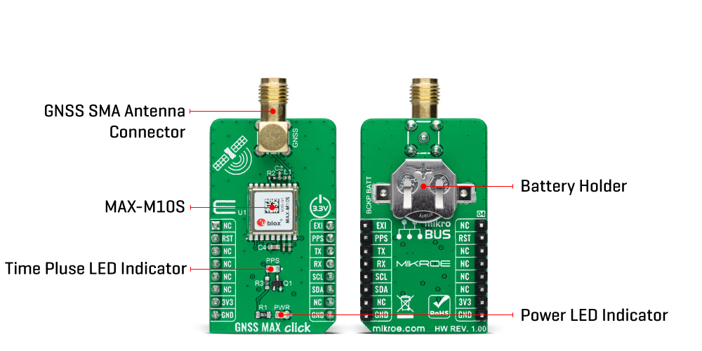
GNSS MAX Click is based on the MAX-M10S (MAX-M10S-00B-01), a high-performance GNSS module from u-blox. The MAX-M10S features the u-blox M10 standard precision GNSS platform and provides exceptional sensitivity and acquisition times for all L1 GNSS signals. It also supports concurrent reception of up to four GNSS (GPS, GLONASS, Galileo, and BeiDou), maximizing position availability, particularly under challenging conditions such as deep urban canyons. The MAX-M10S offers high sensitivity and minimal acquisition times while maintaining low system power. The MAX-M10S module integrates an LNA and a SAW filter in the RF path for maximum sensitivity. Also, it detects jamming and spoofing attempts and reports them to the host so that the system can react to such events. Advanced filtering algorithms mitigate the impact of RF interference and jamming, thus enabling the product to operate as intended.
The u-blox Super-S technology offers great RF sensitivity that improves the dynamic position accuracy by up to 25% with small antennas or in a non-line-of-sight scenario. This Click board™ comes with a configurable host interface that allows communication with MCU using the selected interface. The MAX-M10S can communicate with MCU using the UART interface with commonly used UART RX and TX pins as its default communication protocol operating at 9600bps to transmit and exchange data with the host MCU or using the I2C interface. The I2C interface is compatible with the Fast-Mode allowing a maximum bit rate of 400kbit/s. In addition to these features, it also uses several mikroBUS™ pins. An active-low reset signal routed on the RST pin of the mikroBUS™ socket activates a hardware reset of the system, while the EXT pin routed to the PWM pin on the mikroBUS™ socket represents an external interrupt used for the module
Wake-Up function. It also uses a PPS signal routed on the INT pin of the mikroBUS™ socket alongside a blue LED indicator marked as STATUS used for time pulse signal information and indication. GNSS MAX Click possesses the SMA antenna connector on which an appropriate antenna connects that Mikroe has in its offer for improved range and received signal strength. Also, in the case of the primary supply failure, the module can use a backup supply voltage from a connected battery if you need the Click board™ to be a standalone device. This Click board™ can only be operated from a 3.3V logic voltage level. Therefore, the board must perform appropriate logic voltage conversion before using MCUs with different logic levels. However, the Click board™ comes equipped with a library containing functions and an example code that can be used as a reference for further development.
Features overview
Development board
EasyPIC v7a is the seventh generation of PIC development boards specially designed for the needs of rapid development of embedded applications. It supports a wide range of 8-bit PIC microcontrollers from Microchip and has a broad set of unique functions, such as the first-ever embedded debugger/programmer over USB-C. The development board is well organized and designed so that the end-user has all the necessary elements in one place, such as switches, buttons, indicators, connectors, and others. With four different connectors for each port, EasyPIC v7a allows you to connect accessory boards, sensors, and custom electronics more efficiently than ever. Each part of the EasyPIC v7a development board
contains the components necessary for the most efficient operation of the same board. In addition to the advanced integrated CODEGRIP programmer/debugger module, which offers many valuable programming/debugging options and seamless integration with the Mikroe software environment, the board also includes a clean and regulated power supply module for the development board. It can use various external power sources, including an external 12V power supply, 7-23V AC or 9-32V DC via DC connector/screw terminals, and a power source via the USB Type-C (USB-C) connector. Communication options such as USB-UART and RS-232 are also included, alongside the well-
established mikroBUS™ standard, three display options (7-segment, graphical, and character-based LCD), and several different DIP sockets. These sockets cover a wide range of 8-bit PIC MCUs, from PIC10F, PIC12F, PIC16F, PIC16Enh, PIC18F, PIC18FJ, and PIC18FK families. EasyPIC v7a is an integral part of the Mikroe ecosystem for rapid development. Natively supported by Mikroe software tools, it covers many aspects of prototyping and development thanks to a considerable number of different Click boards™ (over a thousand boards), the number of which is growing every day.

Microcontroller Overview
MCU Card / MCU
Architecture
PIC
MCU Memory (KB)
48
Silicon Vendor
Microchip
Pin count
40
RAM (Bytes)
3328
You complete me!
Accessories
GNSS Active External Antenna is a unique multi-band type of antenna coming from u-blox that is the perfect selection for high precision GNSS applications, which require highly accurate location abilities such as RTK. The ANN-MB-00 is a multi-band (L1, L2/E5b/B2I) active GNSS antenna with a 5m cable and SMA connector. The antenna supports GPS, GLONASS, Galileo, and BeiDou and includes a high-performance multi-band RHCP dual-feed patch antenna element, a built-in high-gain LNA with SAW pre-filtering, and a 5 m antenna cable with SMA connector, and is waterproof.

Used MCU Pins
mikroBUS™ mapper
Take a closer look
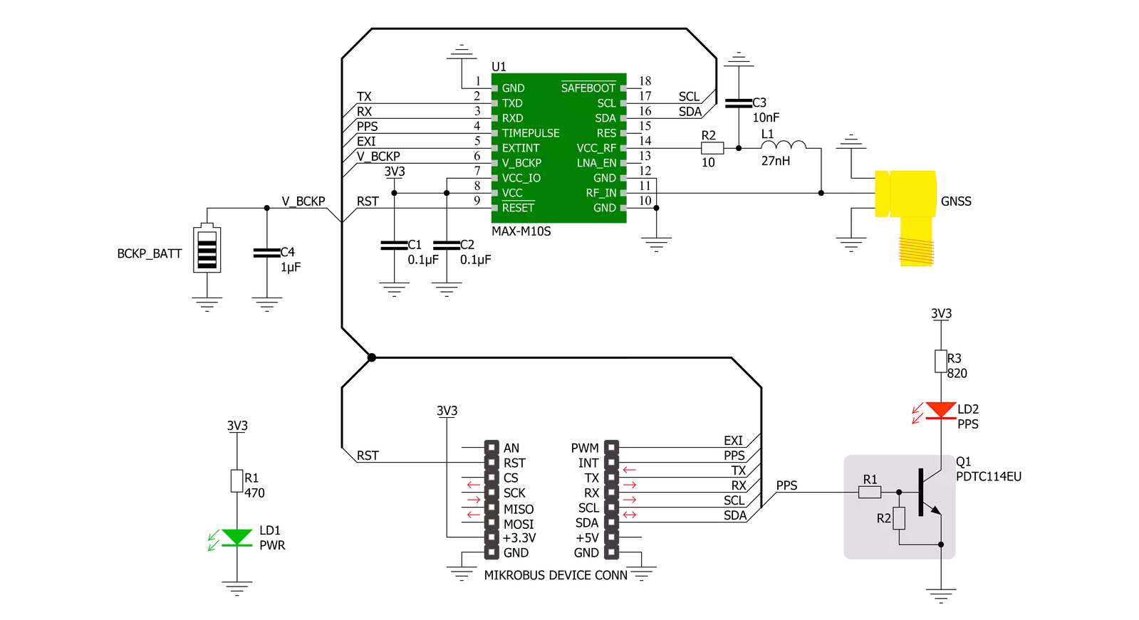
Click board™ Schematic
Step by step
Project assembly

Start by selecting your development board and Click board™. Begin with the EasyPIC v7a as your development board.


Track your results in real time
Application Output
1. Application Output - In Debug mode, the 'Application Output' window enables real-time data monitoring, offering direct insight into execution results. Ensure proper data display by configuring the environment correctly using the provided tutorial.

2. UART Terminal - Use the UART Terminal to monitor data transmission via a USB to UART converter, allowing direct communication between the Click board™ and your development system. Configure the baud rate and other serial settings according to your project's requirements to ensure proper functionality. For step-by-step setup instructions, refer to the provided tutorial.

3. Plot Output - The Plot feature offers a powerful way to visualize real-time sensor data, enabling trend analysis, debugging, and comparison of multiple data points. To set it up correctly, follow the provided tutorial, which includes a step-by-step example of using the Plot feature to display Click board™ readings. To use the Plot feature in your code, use the function: plot(*insert_graph_name*, variable_name);. This is a general format, and it is up to the user to replace 'insert_graph_name' with the actual graph name and 'variable_name' with the parameter to be displayed.

Software Support
Library Description
This library contains API for GNSSMAX Click driver.
Key functions:
gnssmax_generic_read- GNSS MAX data reading function.gnssmax_reset- GNSS MAX reset function.gnssmax_get_pps- GNSS MAX reads timestamp pin state.
Open Source
Code example
The complete application code and a ready-to-use project are available through the NECTO Studio Package Manager for direct installation in the NECTO Studio. The application code can also be found on the MIKROE GitHub account.
/*!
 * @file main.c
 * @brief GNSSMAX Click Example.
 *
 * # Description
 * This example showcases device abillity to read data outputed
 * from device and show it's coordinates and altitude when connected.
 *
 * The demo application is composed of two sections :
 *
 * ## Application Init
 * Initializes host communication modules, additioaln GPIO's used
 * for control of device and resets device.
 *
 * ## Application Task
 * Reads data from device and wait's untill device is connected.
 * While not connected it will log '.'. When conneceted and received
 * data for latitude, longitude, and altitude it will log that data
 * parsed from "GNGGA" command.
 *
 * ## Additional Function
 * - static void gnssmax_clear_app_buf ( void )
 * - static err_t gnssmax_process ( void )
 * - static err_t gnssmax_cmd_parser ( char *cmd )
 * - static err_t gnssmax_element_parser ( char *cmd, uint8_t element, char *element_data )
 *
 * @note
 * For the device to connect it can take it from 1 to 10 minutes.
 * Time to connect is depending on weather.
 *
 * @author Luka Filipovic
 *
 */

#include "board.h"
#include "log.h"
#include "gnssmax.h"

#define PROCESS_BUFFER_SIZE                     700
#define DATA_BUFFER_SIZE                        30

#define RSP_GNGGA                               "GNGGA"
#define RSP_START                               '$'
#define RSP_SEPARATOR                           ','

#define RSP_GNGGA_LATITUDE_ELEMENT              2
#define RSP_GNGGA_LONGITUDE_ELEMENT             4
#define RSP_GNGGA_ALTITUDE_ELEMENT              9

static gnssmax_t gnssmax;
static log_t logger;

static char app_buf[ PROCESS_BUFFER_SIZE ]      = { 0 };
static int32_t app_buf_len                      = 0;
static int32_t app_buf_cnt                      = 0;

static char latitude_data[ DATA_BUFFER_SIZE ]   = { 0 };
static char longitude_data[ DATA_BUFFER_SIZE ]  = { 0 };
static char altitude_data[ DATA_BUFFER_SIZE ]   = { 0 };

err_t last_error_flag;

/**
 * @brief GNSSMAX clearing application buffer.
 * @details This function clears memory of application buffer and reset it's length and counter.
 */
static void gnssmax_clear_app_buf ( void );

/**
 * @brief GNSSMAX data reading function.
 * @details This function reads data from device and concats data to application buffer.
 *
 * @return @li @c GNSSMAX_OK - Read some data.
 *         @li @c GNSSMAX_ERROR - Nothing is read.
 *         @li @c GNSSMAX_ERROR_NO_DATA - Application buffer overflow.
 *
 * See #err_t definition for detailed explanation.
 */
static err_t gnssmax_process ( void );

/**
 * @brief GNSSMAX command data parser.
 * @details This function searches @b app_buf for @b cmd and logs data of that command.
 *
 * @param[in] cmd : Command to parese.
 *
 * @return @li @c GNSSMAX_OK - Parsed data succes.
 *         @li @c GNSSMAX_ERROR - No @b cmd in application buffer.
 *
 * See #err_t definition for detailed explanation.
 */
static err_t gnssmax_cmd_parser ( char *cmd );

/**
 * @brief GNSSMAX element of command data parser.
 * @details This function searches @b app_buf for @b cmd and it's
 *          @b element and copies data to @b element_data buffer.
 *
 * @return @li @c GNSSMAX_OK - Read some data.
 *         @li @c GNSSMAX_ERROR - No @b cmd in application buffer.
 *         @li @c GNSSMAX_ERROR_NO_DATA - No data for @b element in @b cmd.
 *         @li @c GNSSMAX_ERROR_OVERFLOW - Data buffer overflow.
 *
 * See #err_t definition for detailed explanation.
 */
static err_t gnssmax_element_parser ( char *cmd, uint8_t element, char *element_data );

void application_init ( void )
{
    log_cfg_t log_cfg;  /**< Logger config object. */
    gnssmax_cfg_t gnssmax_cfg;  /**< Click config object. */

    /**
     * Logger initialization.
     * Default baud rate: 115200
     * Default log level: LOG_LEVEL_DEBUG
     * @note If USB_UART_RX and USB_UART_TX
     * are defined as HAL_PIN_NC, you will
     * need to define them manually for log to work.
     * See @b LOG_MAP_USB_UART macro definition for detailed explanation.
     */
    LOG_MAP_USB_UART( log_cfg );
    log_init( &logger, &log_cfg );
    log_info( &logger, " Application Init " );
    Delay_ms ( 500 );

    // Click initialization.
    gnssmax_cfg_setup( &gnssmax_cfg );
    GNSSMAX_MAP_MIKROBUS( gnssmax_cfg, MIKROBUS_1 );
    err_t init_flag  = gnssmax_init( &gnssmax, &gnssmax_cfg );
    if ( init_flag == UART_ERROR )
    {
        log_error( &logger, " Application Init Error. " );
        log_info( &logger, " Please, run program again... " );

        for ( ; ; );
    }

    gnssmax_default_cfg( &gnssmax );

    last_error_flag = GNSSMAX_OK;
    log_info( &logger, " Application Task " );
    Delay_ms ( 500 );
}

void application_task ( void )
{
    gnssmax_process();

    err_t error_flag = gnssmax_element_parser( RSP_GNGGA, RSP_GNGGA_LATITUDE_ELEMENT,
                                             latitude_data );

    error_flag |= gnssmax_element_parser(  RSP_GNGGA, RSP_GNGGA_LONGITUDE_ELEMENT,
                                         longitude_data );

    error_flag |= gnssmax_element_parser(  RSP_GNGGA, RSP_GNGGA_ALTITUDE_ELEMENT,
                                         altitude_data );


    if ( error_flag == GNSSMAX_OK )
    {
        if ( last_error_flag != GNSSMAX_OK )
        {
            log_printf( &logger, "\r\n" );
        }
        log_printf( &logger, ">Latitude:\r\n - deg: %.2s \r\n - min: %s\r\n",
                    latitude_data, &latitude_data[ 2 ] );

        log_printf( &logger, ">Longitude:\r\n - deg: %.3s \r\n - min: %s\r\n",
                    longitude_data, &longitude_data[ 3 ] );

        log_printf( &logger, ">Altitude:\r\n - %sm\r\n",
                    altitude_data );

        log_printf( &logger, "----------------------------------------\r\n" );
    }
    else if ( error_flag < GNSSMAX_ERROR )
    {
        if ( last_error_flag == GNSSMAX_OK )
        {
            log_printf( &logger, "Waiting for data " );
        }
        log_printf( &logger, "." );
    }

    if ( error_flag != GNSSMAX_ERROR )
    {
        last_error_flag = error_flag;
        gnssmax_clear_app_buf(  );
    }
}

int main ( void )
{
    /* Do not remove this line or clock might not be set correctly. */
    #ifdef PREINIT_SUPPORTED
    preinit();
    #endif

    application_init( );

    for ( ; ; )
    {
        application_task( );
    }

    return 0;
}

static void gnssmax_clear_app_buf ( void )
{
    memset( app_buf, 0, app_buf_len );
    app_buf_len = 0;
    app_buf_cnt = 0;
}

static err_t gnssmax_process ( void )
{
    int32_t rx_size;
    char rx_buff[ PROCESS_BUFFER_SIZE ] = { 0 };

    rx_size = gnssmax_generic_read( &gnssmax, rx_buff, PROCESS_BUFFER_SIZE );

    if ( rx_size > 0 )
    {
        int32_t buf_cnt = 0;

        if ( ( app_buf_len + rx_size ) > PROCESS_BUFFER_SIZE )
        {
            gnssmax_clear_app_buf(  );
            return GNSSMAX_ERROR_NO_DATA;
        }
        else
        {
            buf_cnt = app_buf_len;
            app_buf_len += rx_size;
        }

        for ( int32_t rx_cnt = 0; rx_cnt < rx_size; rx_cnt++ )
        {
            if ( rx_buff[ rx_cnt ] != 0 )
            {
                app_buf[ ( buf_cnt + rx_cnt ) ] = rx_buff[ rx_cnt ];
            }
            else
            {
                app_buf_len--;
                buf_cnt--;
            }
        }
        return GNSSMAX_OK;
    }
    return GNSSMAX_ERROR;
}

static err_t gnssmax_cmd_parser ( char *cmd )
{
    err_t ret_flag = GNSSMAX_OK;

    if ( strstr( app_buf, cmd ) != GNSSMAX_OK )
    {
        char * __generic_ptr gngga_ptr;

        gngga_ptr = strstr( app_buf, cmd );

        while ( strchr( gngga_ptr, RSP_START ) == GNSSMAX_OK )
        {
            gnssmax_process();
        }

        for ( ; ; )
        {
            log_printf( &logger, "%c", *gngga_ptr );
            gngga_ptr++;

            if ( ( *gngga_ptr == RSP_START ) )
            {
                break;
            }
        }
    }
    else
    {
        ret_flag = GNSSMAX_ERROR;
    }

    return ret_flag;
}

static err_t gnssmax_element_parser ( char *cmd, uint8_t element, char *element_data )
{
    err_t ret_flag = 0;


    if ( strstr( app_buf, cmd ) != 0 )
    {
        uint8_t element_cnt = 0;
        char data_buf[ DATA_BUFFER_SIZE ] = { 0 };
        uint8_t data_cnt = 0;
        char * __generic_ptr gngga_ptr;

        gngga_ptr = strstr( app_buf, cmd );

        while ( strchr( gngga_ptr, RSP_START ) == GNSSMAX_OK )
        {
            gnssmax_process();
        }

        for ( ; ; )
        {
            if ( ( *gngga_ptr == RSP_START ) )
            {
                ret_flag = GNSSMAX_ERROR_NO_DATA;
                break;
            }

            if ( *gngga_ptr == RSP_SEPARATOR )
            {
                if (element_cnt == element)
                {
                    if ( data_cnt == 0 )
                    {
                        ret_flag = GNSSMAX_ERROR_NO_DATA;
                    }
                    strcpy( element_data, data_buf );
                    break;
                }

                element_cnt++;
            }

            if ( ( element == element_cnt ) && ( *gngga_ptr != RSP_SEPARATOR ) )
            {
                data_buf[ data_cnt ] = *gngga_ptr;
                data_cnt++;

                if ( data_cnt >= DATA_BUFFER_SIZE )
                {
                    ret_flag = GNSSMAX_ERROR_OVERFLOW;
                    break;
                }
            }

            gngga_ptr++;
        }
    }
    else
    {
        ret_flag = GNSSMAX_ERROR;
    }

    return ret_flag;
}

// ------------------------------------------------------------------------ END


